Table of Contents
Advertisement
Advertisement
Table of Contents

Summary of Contents for Survision Micropak 3
- Page 1 LPR Camera Installation & Settings Manual...
- Page 2 Micropak: Version 3 and higher Visipak: Version 4 and higher The SURVISION cameras facilitate a large number of applications for the road traffic, access control and public safety sectors. So that the LPR cameras can correctly carry out their required function, their performance level is crucial.
-
Page 3: Table Of Contents
2.1- Assembly and power supply of the NANOPAK Totem 2.1.1 - Assembly procedure with weak electric current 2.1.2 - Assembly procedure with strong electric current 2.1.3 - Installation procedure for totems assembled by SURVISION in factory 2.2 - Assembly of MICROPAK 2.2.1 - Characteristics of the MICROPAK 2.2.2 - Attachment of the support bracket to the wall using the fixation kit... -
Page 4: Installation Location
1 - Installation location... -
Page 5: Possible Installation Locations
1.1 - Possible installation locations The SURVISION cameras can read from both front and rear, i.e. : • The NANOPAK can be installed in a barrier column or in a Totem. • The MICROPAK and the VISIPAK can be installed on a pole, on a wall, on a ceiling or on a gantry. -
Page 6: Specific Installation Rules For Car-Parks And For Normal Toll Installation When Reading From The Front
Where cameras are installed before being connected to the power supply and the computing network, it is essential that the connectors be protected against water entry. Installation location rules for maximum performance: • Installation of the camera on the same side as the terminal stand, •... -
Page 7: Specific Rules For Ceiling Installation When Reading From The Front
1.4 - Specific rules for ceiling installation when reading from the front The camera must be installed at a horizontal distance “X”, equal to half of H, the installation height less the height of the barrier bar. The space given by the distance x ensures that the plate is read before the plate arrives at the barrier, without the barrier appearing in the image. -
Page 8: Assembly
Assembly... - Page 9 HANDLING PRECAUTIONS When handling the NANOPAK Totem, please take the required precautions and pay particular attention to the following diagrams: Attention, hot surface Warning about a risk due to hot surfaces during the handling, for example, of machines, tools, etc… The symbol indicates a dangerous situation which, if the correct behavior is not adopted, can lead to slight bodily harm and possible material damage.
-
Page 10: Assembly And Power Supply Of The Nanopak Totem
2 .1 - Assembly and power supply of the NANOPAK Totem 2 .1.1 - Assembly procedure with weak electric current The assembly with weak current corresponds to a 24V power supply located on the outside of the totem. 1. Remove rear part. The NANOPAK is already installed in the Totem on delivery. -
Page 11: Assembly Procedure With Strong Electric Current
The Ethernet cable to be used, which is not provided by SURVISION must be at least Cat5e in accordance with local regulations. The connection to the electricity supply on the terminal is carried out according to the... - Page 12 3.1 Install the backplane in the totem Step 4 SURVISION can carry out this operation. See 2.1.3 screws backplane as well as the NANOPAK by adjusting the inclination...
-
Page 13: Installation Procedure For Totems Assembled By Survision In Factory
2.1.3 Installation procedure for totems assembled by SURVISION in factory The totems assembled in the factory by SURVISION are delivered as below: The installer has to assemble: - The power supply cable in strong current on the terminal - The Ethernet cable... -
Page 14: Assembly Of Micropak
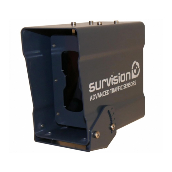
2.2 - Assembly of MICROPAK 2.2.1 Characteristics of the MICROPAK The Ethernet and power supply cables are provided by SURVISION (Deliveries in the USA only include the power cables). The power cable measures 3m. - Power supply : 24 VDC... -
Page 15: Attachment Of The Support Bracket To The Wall Using The Fixation Kit With Angular Displacement Provided By Survision
2.2.2 Attachment of the support bracket to the wall using the fixation kit with angular displacement provided by SURVISION Step 1 1.1 - Fit the cradle to the front of the sunvisor, on the lower part, using the screws of diametre M5 1.2 - First attach the three screws (but... -
Page 16: Fixation Of Support Bracket To The Ceiling Using The Fixation Kit With
2.2.3 Fixation of support bracket to the ceiling using the fixation kit with angular displacement provided by SURVISION Step 1 1.1 - Fit the cradle to the front of the... - Page 17 Step 2 Fit the cradle and the camera to the bracket using the two screws of diameter M6 Step 3 Adjust the plane of the camera so that the plates appear horizontal in the image using the central screw under the bracket joint...
-
Page 18: Assembly Of Amphenol Connector
2.2.5 Diagram of MICROPAK power supply connector This cable provide SURVISION. The MICROPAK power supply connecter allows us to connect the camera to other functions such as the IO In and Out, the RS 485 as well as the connection to a LUMIPAK for additional illumination. -
Page 19: Assembly Of Visipak
2.3 - Assembly of VISIPAK 2.3.1 VISIPAK features The Ethernet and power supply cables are provided by SURVISION. The power supply cable is 3m/9,84 ft in length. - Power supply: 24 VDC - Consumption: Maximum 60W/Average 40W The options available with the VISIPAK are: •... -
Page 20: Support Bracket Installation Procedure
2.3.2 Support bracket installation procedure The VISIPAK can be mounted from underneath as illustrated below or by above by using the holes of the visor screws to attach the bracket. Step 2 Step 1 Fit the bracket into place, fit and tighten Turn over the VISIPAK and fit the rubber the supplied screws plate... -
Page 21: Particular Case Of Survision Graduated Angle Support Bracket For Visipak
2.3.3 Particular case of SURVISION graduated angle support bracket for VISIPAK The adjustment is carried graduated angle Prior adjustment helps save out by opening the screws bracket allows prior time during installation and changing the angle installation adjustment (in and limit the time that... -
Page 22: Assembly Of Amphenol Connector For Visipak
2.3.4 Assembly of AMPHENOL connector for VISIPAK Step 1 Step 2 Step 3 Step 4 Step 6 Step 5... -
Page 23: Assembly Of The Visor
2.3.5 Assembly of the visor Step 2 Step1 Install the visor and tighten with the four Screw the small struts to the top screws provided... -
Page 24: Aiming/Settings Adjustment
Aiming/Setting adjustment... -
Page 25: Procedure Of Adjustment Of Survision Cameras
130 and 170 pixels, with the plate in Illustration 1 the center of the reading zone (Illustration 1). For the MICROPAK 3, apply exclusion zones so that the reading occurs within the distance range recommended for the particular camera model (Illustration 2). - Page 26 The camera adjustment is now complete. Save the conguration in a CDKMSG file (menu “settings”, “Save Conguration to File”) and store it carefully to be able to recharge it if necessary for maintenance purposes. Unlock the camera and wait for the VSS welcome screen to prevent the risk of losing the configuration.
-
Page 27: Maintenance
Maintenance... -
Page 28: Preventative Maintenance
The update is carried out using a software tool provided by SURVISION. Once started, the operation consists simply in inputting the IP address of the camera to be updated and clicking on OK. -
Page 29: Curative Maintenance
5. Carry out the firmware update. If after having carried out all these operations, the sensor is not satisfactory, it may be necessary to return it for repairs. In case of doubt, please contact our support team: www.survision.fr Technical Support button on welcome page... -
Page 30: Rma Procedure
4.4 - RMA procedure Faulty sensors must be sent back to SURVISION (address below) without any need of an RMA number. Each camera return must absolutely be declared on my.survision.fr and the returned camera will not be processed if this breakdown declaration is not carried out. - Page 31 SURVISION 22, rue d’Arras 92000 NANTERRE FRANCE Tel. +33 1 47 51 04 80 contact@survision.fr SURVISION 11251 NW 20th St #116 Miami, FL 33172 Tel. +1 (786) 362.5471 contact@survisiongroup.com...
Need help?
Do you have a question about the Micropak 3 and is the answer not in the manual?
Questions and answers