Table of Contents
Advertisement
Quick Links
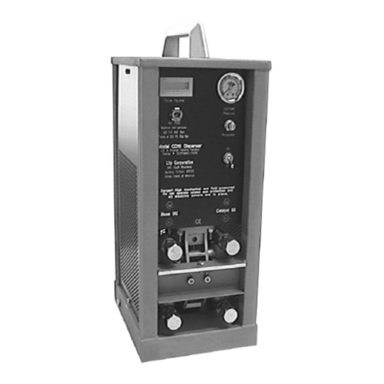
CD15
Operation and Service Manual
Lily Corporation
240 S. Broadway
Aurora, Illinois 60505-4205
United States of America
Ph: 630-892-0860
Fax:630-892-5623
www.lilycorp.com
1
Product Warranty and Disclaimer
The Resin Supply
Ratio Assurance Check
Parts Diagrams
Troubleshooting
Troubleshooting
2
2
3
3
4
5
6
6
7-8
7
8-9
10
11
12
12
13
13-14
15-17
17-18
24-39
40-41
Ver. 1.6
Advertisement
Table of Contents

Subscribe to Our Youtube Channel
Related Manuals for Lily Corporation CD15


Summary of Contents for Lily Corporation CD15
-
Page 1: Table Of Contents
CD15 Operation and Service Manual Product Warranty and Disclaimer Safety Precautions The Resin Supply Fluid Connections Filling The Supply Tanks Monitoring The Resin Supply The Air Supply Connections & Requirements Operation To Begin With Dispensing Shut Down Clean - Up... -
Page 2: Safety Precautions
EXPRESS WARRANTY AND DISCLAIMER OF IMPLIED WARRANTIES Lily Corporation unconditionally guarantees its products to be free of defects in material or workmanship and further warrants that, for a period of three months from date of factory shipment, its products will meet the performance criteria stated in Lily Corporation’s publications. -
Page 3: Fluid Connections
Connect the fluid hose from the A tank (base resin) at the lower left hand fitting (base resin inlet) on the front of the CD15 dispenser. Connect the B tank (catalyst) at the lower right hand fitting (catalyst inlet) as you view the dispenser. -
Page 4: Monitoring The Resin Supply
PH of greater than 10 or less than 1. Monitoring The Resin Supply If either resin container is depleted, the CD15 will dispense the remaining component. Air is a fluid, and the system cannot tell the difference. In the case of crack injection, the result may be very costly, as it is unlikely that the error can be fully corrected. -
Page 5: The Air Supply
The Air Supply Connections & Requirements The air connections are the ‘press to connect’ variety. The connection is made by firmly inserting the tube end into the fitting. It is released by pulling the fitting collar firmly back against the fitting body while pulling the tube from the fitting. - Page 6 Bulkhead Connection at Handtruck Air Compressor Connection Air Lines to Pressure Vessels Connection to CD15 An excess of tubing is provided with this assembly. Trim the assembly to fit your installation. Ver. 1.6...
-
Page 7: Operation
Operation To Begin With Purge the air hose from the compressor of water or other contaminants. ● Switch the dispenser cabinet off. ● Point the selector valve handles on the material tanks toward the tubing. ● ● Fix a mixer or manifold and fluid valve at the material outlet fittings. Reduce the dispenser air pressure to zero by turning the regulator counter ●... -
Page 8: Shut Down
Set the tank aside until time to clean-up. 3. Next “burp” the CD15. To do this simply dispense a few ounces of material into a waste container immediately after removing the mixer from the dispenser. This will flush any base resin that may have entered the catalyst fitting or valve. -
Page 9: Clean Up
Ratio Assurance Test WARNING! The CD15 contains moving parts which are by definition wearing parts. Critical components are wearing from the moment you energize the system. It is absolutely essential that this wear be anticipated and monitored to assure proper ratio dispensing. Key personnel must become familiar with the following procedure for monitoring the wear of metering seals, for if it does not become routine, improperly metered material will result. - Page 10 Operation Ratio Assurance Test Stage II: To determine if the Coco inlet valve seals are leaking in the direction of normal flow. 1. Turn the pressure regulator counterclockwise until no pressure is registered on the gauge. 2. Flip the dispenser switch “on”. [This will open the outlet valves and close the inlet valves.] 3.
-
Page 11: Changing Ratio
Operation Changing Ratio Ratio is determined by the relative diameters of the catalyst and base pistons. If the ratio is 1:1, both metering pistons will be the same. However, with any other ratio, the catalyst metering piston will be of a smaller diameter. Ratio is therefore changed by exchanging one catalyst metering assembly for another. -
Page 12: The System And How It Works
THE SYSTEM AND HOW IT WORKS The Fluid Circuit The resin components are pressurized within vessels (A) or by pumps. Pressurized, the components flow through open inlet valves (B) to enter their respective metering cylinders (C). The metering pistons (D) are extended by the resin pressure until they bear against the main air cylinder end cap (E). -
Page 13: The Fill Sensors
SERVICING THE SYSTEM If the CD15 is properly maintained, service will involve little more than routine replacement of dynamic seals exposed to material being dispensed. The frequency of seal replacement will depend upon the material dispensed. Thousands of gallons of non-abrasive resin with good lubricity may be dispensed with little, if any, service;... -
Page 14: Coco Module
SERVICING THE SYSTEM The COCO Module When a ratio assurance check reveals a need for seal replacement at the Coco module, it is not necessary to replace all of the seals within the module. Rather, replace only those seals metering the same component. Resin components differ dramatically in terms of their abrasiveness, so the wear of the seal managing one component is seldom an indication that the seals on the opposite side are similarily worn. - Page 15 SERVICING THE SYSTEM Disassembly 6. Use a 3/16” allen 5. Grasp the coupler wrench to remove the shaft (M-581) with a four screws securing the cushioned tool, and valve to the spacer gently work it and its block. If they do not bushing (M-802) from separate easily, tap the cavity.
-
Page 16: Assembly
SERVICING THE SYSTEM Assembly 1. Fit the seal spring 2. Place the washer (S- (S-330) into the pocket 329) over the spring. with its concave side Nudge it to be certain toward the ball. that both it and the spring are fully seated. - Page 17 SERVICING THE SYSTEM Assembly 12. Install the 11. Carefully insert the retaining ring (P-505). coupler shaft (M-581), Note that one side of bronze bushing (M-802) the ring has slightly and washer (P-469) into rounded edges, while the housing. the other side has a sharp square edge.
-
Page 18: Metering Cylinders
SERVICING THE SYSTEM 17. With the gage posts fully inserted, snug the bolts securing the inlet valve bodies to the center block. Then further tighten the bolts in sequence, moving from corner to corner across the valve until all are tight. - Page 19 SERVICING THE SYSTEM Replace the seal 8. Inspect the piston with its spring groove pad. If it is torn or towards the bottom worn, replace it by of the piston. removing its retaining screw. Apply a drop of blue Loctite thread seal or equal to the 9.
-
Page 20: The Control Circuit
The Control Circuit The CD15 is entirely pneumatic. It uses compressed air for its control circuit, as well as for energy to dispense. An air circuit is nearly as reliable as an electric circuit if the air supply is clean, dry, and free of lubricants and additives, other than those applied by the manufacturer. - Page 21 SERVICING THE SYSTEM The Control Circuit Ver. 1.6...
- Page 22 SERVICING THE SYSTEM The Control Circuit Diagram I Diagram I The switch is on, energizing port “H” at the lower end cap. The system is poised to dispense. However, it cannot do so until the material metering cylinders have filled, fully extending their pistons to seal off the air signal escaping through vents “V”.
- Page 23 SERVICING THE SYSTEM The Control Circuit Diagram II Diagram II The metering cylinders have filled, fully extending both of the metering pistons to close off vents “V”. A signal has emerged from “O” to the Twin Valve at port A4, venting port A3, and energizing Port A2.
- Page 24 SERVICING THE SYSTEM The Control Circuit Diagram III Diagram III The switch is off. The on/off switch directs the signal to the “Or” element, from where it delivers a signal to the A1 port of the Twin Valve (M-017). This signal shifts the valve to provide a signal from its A3 port, and vent the A2 port.
-
Page 25: Parts Diagrams
Parts Diagrams Ver. 1.6... - Page 26 Parts Diagrams Ver. 1.6...
- Page 27 Parts Diagrams Ver. 1.6...
- Page 28 Parts Diagrams AC-2 BOTTOM END CAP PARTS LIST ITEM PART NUMBER DESCRIPTION M-613 A/C END CAP - BOTTOM - CD15 S-323 SEAL - WIPER - 7/8 ROD BUSHING - AIR CYLINDER CD15 P-378 S-317 SEAL - O-RING S-325 WASHER - TROUT VALVE...
- Page 29 Parts Diagrams Ver. 1.6...
- Page 30 Parts Diagrams Ver. 1.6...
- Page 31 Parts Diagrams Ver. 1.6...
- Page 32 Air Logic Diagram Ver. 1.6...
- Page 33 Parts Diagrams Ver. 1.6...
- Page 34 Parts Diagrams Ver. 1.6...
- Page 35 Parts Diagrams Ver. 1.6...
- Page 36 S-013 LID SEAL P-762 1 GAL. PURGE TANK P-691 PURGE TANK DIP TUBE M-540 OUTLET MANIFOLD S-160 MALE QUICK CONNECT P-496 ELBOW 3/8" JIC X 3/8" STRAIGHT THREAD S-307 SEAL LOK - STRT THREAD UNION 1/2" c:\inventor data\dispensers\cd15\a-118-2new.idw Ver. 1.6...
- Page 37 Parts Diagrams Ver. 1.6...
- Page 38 Parts Diagrams Ver. 1.6...
- Page 39 Parts Diagrams Ver. 1.6...
- Page 40 Parts Diagrams Ver. 1.6...
- Page 41 TROUBLE SHOOTING Spurts of air, or air bubbles in the material….Check the material level. Some air may enter the resin as it cavitates just before it is depleted. This is especially true of viscous material. Air bubbles in the resin….Check the resin tank for an air leak into the stem at its interior fitting. Incorrect ratio……………..Conduct ratio assurance check to confirm valve performance.
- Page 42 If you cannot correct the problem, contact Lily Corporation with an exact description of how the various components are responding. If possible, phone with the unit, air, tools, and resin information at hand.
Need help?
Do you have a question about the CD15 and is the answer not in the manual?
Questions and answers