Table of Contents
Advertisement
Quick Links
Advertisement
Table of Contents

Summary of Contents for Spectra Engineering RELM BK RADIO MXACU
- Page 1 Automatic Base Station Changeover Unit MXACU Technical Manual...
- Page 3 Service: (800) 422-6281 www.RELM.com Manual Revision 1.1.0 September 2006 In order to continually improve our products, Spectra Engineering Pty Ltd reserves the right to alter, without notice and at any time, the equipment and specifications described in this document. All performance figures quoted are typical and are subject to normal manufacturing and service tolerances.
- Page 4 MXACU Technical Manual This page left blank intentionally © SPECTRA ENGINEERING 2005 Revision 1.1.0...
- Page 5 MXACU Record Of Changes Any changes to this manual are recorded on this list. Spectra Engineering may issue replacement pages to you from time to time. If any updates are issued, you will also receive a replacement for this page.
- Page 6 The following conditions are not covered by the warranty of the MXACU. Please ensure that the MXACU is not subject to; 1. Over voltage or Reverse Power Supply Voltage. 2. Operation in locations subject to abnormal environmental conditions such as extreme temperatures or ingress of moisture. © SPECTRA ENGINEERING 2005 Revision 1.1.0...
-
Page 7: Table Of Contents
Rem ote Control ..................22 Serial Commands ............... 22 Networked Operation ..............22 3.2.1 Network Commands ............22 Options ....................24 DTMF Remote control operation ..........24 PSTN Modem................24 Ethernet Port................24 Technical Description ................25 © SPECTRA ENGINEERING 2005 Revision 1.1.0... - Page 8 Diagnostic Menu ................ 29 Automatic tests ..................30 Receiver..................30 Transmitter ................. 30 DC power ................... 31 Base Radio Alarms ..............31 Automatic Scheduling ..............31 Appendices ..................... 32 Specifications ................32 Drawings ..................32 © SPECTRA ENGINEERING 2005 Revision 1.1.0...
- Page 9 Table 6-1 Serial Port Communication Parameters ..........27 Table 8-1 General Specifications ................32 Table 8-2 Drawings ....................32 List of Figures Figure 1-1 ACU Front Panel..................8 Figure 1-2 MX800 Rear Panel ................. 10 © SPECTRA ENGINEERING 2005 Revision 1.1.0...
-
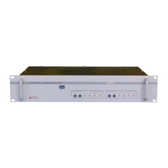
Page 10: General Description
Base B Fault Indicator Base A Fault Indicator Base B Active Indicator Base A Power Indicator Base B Self Test Button Base A Status Indicator Base B Select Button Figure 1-1 ACU Front Panel © SPECTRA ENGINEERING 2005 Revision 1.1.0... -
Page 11: Front Panel Indicators
ACU. Please refer to Table 1-2 for the function of this connector. Note You must not have any equipment plugged into the rear serial connector if you want to use this connector for serial communication with the ACU. © SPECTRA ENGINEERING 2005 Revision 1.1.0... -
Page 12: Rear Panel
Table 1-2 on the following page explains each connector on the rear of the ACU’s function. © SPECTRA ENGINEERING 2005 Revision 1.1.0... -
Page 13: Table 1-2 Rear Panel Connections
When the optional modem is fitted, this connects to a standard telephone line using this port. RJ45 ETHERNET When the Ethernet option is fitted, this connector provides a standard 10 Base-T/100 Base-Tx network port. Table 1-2 Rear Panel Connections © SPECTRA ENGINEERING 2005 Revision 1.1.0... - Page 14 MXACU Technical Manual This page left blank intentionally © SPECTRA ENGINEERING 2005 Revision 1.1.0...
-
Page 15: Installation And Operation
If you intend to install the radio in an equipment rack consult the suppliers instructions for your system. Spectra Engineering strongly recommends that the ACU be secured into the rack system using four screws through the mounting holes in the front panel near the handles. -
Page 16: Power Supply
+12V DC Power Input B (+13.8V) DC supply input diode OR-ed +12V DC Power Input C (+13.8V) DC supply input diode OR-ed 2,4,6 Power negative - Chassis GND Table 2-1 Power Supply Connector Pinout © SPECTRA ENGINEERING 2005 Revision 1.1.0... -
Page 17: Rs232 A/B Ports
Raw Fwd voltage input DC Supply Voltage Raw DC supply input Reverse TX Power Raw Rev voltage input TX Tone This is an AF output from the ACU Table 2-3 Monitor A/B Port Pinout © SPECTRA ENGINEERING 2005 Revision 1.1.0... -
Page 18: Line Io A/B Ports
Connect to Pin 13 of appropriate MX800 CN1 Mute Connect to Pin 14 of appropriate MX800 CN1 RX VF Audio 600ohm Connect to Pin 15 of appropriate MX800 CN1 Table 2-4 Line IO A/B Connector Pinout © SPECTRA ENGINEERING 2005 Revision 1.1.0... -
Page 19: Line I/O Common Port
2/4 wire common port. Connector: RJ45 Socket (8P8C) Pins Function Note 1 to 8 Various Dependent on MX800 option board if fitted. Table 2-6 Base A/B Balanced Connector Pinout © SPECTRA ENGINEERING 2005 Revision 1.1.0... -
Page 20: 2/4 Wire Common Port
Active = fault detected Base ‘B’ fault output Active = fault detected Inactive = ‘A’, Active = ‘B’ Current selected output ACU health output Toggles @ 1Hz while healthy Table 2-8 Digital I/O Connector Pinout © SPECTRA ENGINEERING 2005 Revision 1.1.0... -
Page 21: Operation
2.2.4 Switching between Auto and Locked Mode Press and hold the Select switch on the front panel for longer than three seconds to toggle between Locked and Auto modes. If you wish to avoid © SPECTRA ENGINEERING 2005 Revision 1.1.0... -
Page 22: Switching Base Radios Manually
VSWR. It will clear any transmitter faults previously sensed. If the base to be tested is not currently selected, the ACU will switch over before testing and then switching back to the selected base after testing. © SPECTRA ENGINEERING 2005 Revision 1.1.0... -
Page 23: Resetting Alarms
LED will light. You can also reset the fault alarms using a serial command described in section 3.1 or by turning off the faulty base station’s power and turning it back on. © SPECTRA ENGINEERING 2005 Revision 1.1.0... -
Page 24: Remote Control
Only the addressed ACU will respond when correctly addressed. 3.2.1 Network Commands The commands shown in Table 3-1 above can be directed over a serial network by adding the preset MXACU ID into the command after the first © SPECTRA ENGINEERING 2005 Revision 1.1.0... -
Page 25: Table 3-2 Network Serial Commands
Warm start ACU (Reset) ACUnnMN Enter ACU set-up mode Table 3-2 Network Serial Commands The letters “nn” shown in each command correspond to the ACU network identity. Valid values are from 00 to 99. © SPECTRA ENGINEERING 2005 Revision 1.1.0... -
Page 26: Options
RF channel of the MX800. Self tests and base station changeover can be executed using DTMF commands. Please contact Spectra Engineering regarding this option. PSTN Modem The PSTN Modem option allows technical personnel to control all ACU functions using a PC and modem over a standard telephone line. -
Page 27: Technical Description
IC1 drives pin 1 of IC19 high when base station B is routed and pin 1 is low when base A is routed. Each RS232 port on the ACU has it’s own RS232 driver and receiver pair. © SPECTRA ENGINEERING 2005 Revision 1.1.0... -
Page 28: Real-Time Clock
5.10 PSTN Modem The optional modem is fitted to the mother board adjacent to SK1 and fits into connectors located around IC14. It is directly interfaced to IC2, the DUART. All handshake lines are connected. © SPECTRA ENGINEERING 2005 Revision 1.1.0... -
Page 29: Configuration
Entering the ‘C’ character from the set-up menu displays the configuration menu. From this menu, you can navigate to various other parameter setting menus. 6.3.1 Receiver Parameters Various receiver test parameters need to be set for the automatic receive monitoring. © SPECTRA ENGINEERING 2005 Revision 1.1.0... -
Page 30: Hardware Logic Parameters
If the M wire function is to be tested, select this option to toggle between Y for enabled and N for disabled. If enabled, the ACU will check for correct M wire operation by comparing the M wire output of both connected © SPECTRA ENGINEERING 2005 Revision 1.1.0... -
Page 31: Clock Settings
On this screen, you will see the current date, time and site temperature, which base radio is selected and what mode. Further down, the diagnostic report for each base radio. Pressing any key returns to the previous menu. © SPECTRA ENGINEERING 2005 Revision 1.1.0... -
Page 32: Automatic Tests
Whenever a self test is initiated either remotely or locally, any transmitter fault alarms are reset and the result of the self test will generate a new fault alarm if one is still apparent. © SPECTRA ENGINEERING 2005 Revision 1.1.0... -
Page 33: Dc Power
A schedule to switch them over every midnight for example could be programmed to accommodate this. Please contact Spectra Engineering regarding this feature. © SPECTRA ENGINEERING 2005 Revision 1.1.0... -
Page 34: Appendices
Main board IO circuit diagram CS401-2 Main board Logic circuit diagram CS402-1 Daughter board circuit diagram CS403-1 Display board circuit diagram Main board component legend Daughter board component legend Display board component legend Table 8-2 Drawings © SPECTRA ENGINEERING 2005 Revision 1.1.0... - Page 35 MX800 MX800 'A' Equipment 'B' Equipment LINE I/O 4W E/M LINE MONITOR RS232 LINE I/O 4W E/M LINE MONITOR RS232 Alarm 1 Rptr Enable Alarm 1 Rptr Enable Alarm 2 RX Talk 4W TX RSSI TX DATA Alarm 2 RX Talk 4W TX RSSI TX DATA...
- Page 36 MX800 BASE STATION 'A' RS232 A MXACU CHANGEOVER UNIT BASE A TX 2/4 WIRE MONITOR A POWER 2/4/ WIRE LINE I/O BASE A COMMON ETHERNET BASE A COMMON TX RS232 B 2/4 WIRE LINE I/O LINE I/O RS232 BASE B PSTN BASE B COMMON...
- Page 37 IC18 B-DCV IC16 ST232 ST232 100n 100n 100n 100n 100n SKEB CN2B B-TONE TR26 B-FWD 100n BC857 B-REV 100n IC19 470R TXD1 T1 IN T1 OUT TO MX800 B 74HC157 TR12 B-DISPTT MONITOR PORT A-RXDATA BC847 T1 OUT T1 IN T2 IN T2 OUT T2 OUT...
- Page 38 100n 100n IC14 74HC175 74HC541 100K x 4 IC13 OUT1 LM3485 OUT2 OUT3 TTREN OUT4 39K 1% 220uH TXAF 100p 12K 1% 2200u 25V 100n 100n 100K 820R 1% 100n IC11C MT8870 100n NTGS3455T1 220uH 220uH 390K 100n RXAF OSC1 100u 25V 100n 3.57954 MHz...
- Page 39 CN1A8 CN201A MX800 A LINE I/O DB15M CN1A8 TTR Enable CN1A15 RX 600ohm CN1A14 CN1A7 RX Talk CN1A14 Mute CN1A6 CN1A6 ALM1 CN1A13 TX DC in CN1A5 CN1A5 ALM3 HDR201 CN1A12 CN1A12 CN1A4 Discriminator CN1A11 TX Talk CN1A1 CN1A3 RX Low imp CN1A2 TX Loop CN1A9...
- Page 40 D301 D302 D303 D304 D305 D306 D307 D308 GREEN GREEN AMBER AMBER AMBER AMBER A Active B Active A Pwr B Pwr A Fault B Fault A Error B Error HDR1 Select A Select B Test A Test B TITLE DATE REVISION DATE...
Need help?
Do you have a question about the RELM BK RADIO MXACU and is the answer not in the manual?
Questions and answers