Table of Contents
Advertisement
Quick Links
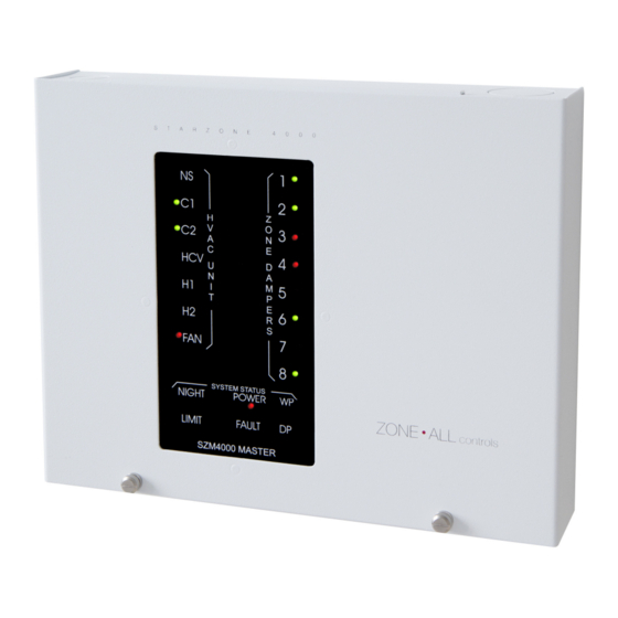
Starzone 4000 Master Control Panel
Figure 2.1 Master Control Panel
The heart of the Starzone 4000 system is the Starzone Master controller
(SZM-4000). Each AHU that is to be zoned will have its own SZM-4000
Master control panel and each panel can operate independently or be
networked together via a 3-wire, RS485 communication bus back to a
central PC.
To make servicing the SZM-4000 Master easier, the controller has two
parts: a motherboard, which has all the connectors for field wiring, and an
electronic daughter board which plugs into the motherboard.
Advertisement
Table of Contents

Summary of Contents for Zone-All Controls Starzone 4000 Master
- Page 1 Starzone 4000 Master Control Panel Figure 2.1 Master Control Panel The heart of the Starzone 4000 system is the Starzone Master controller (SZM-4000). Each AHU that is to be zoned will have its own SZM-4000 Master control panel and each panel can operate independently or be networked together via a 3-wire, RS485 communication bus back to a central PC.
- Page 2 SZM-4000 Master Daughter Board Figure 2.2 Mother and Daughter Boards Swapping out a Master daughter board with a known good board is a simple and time efficient method of confirming whether or not a problem exists with the daughter board or elsewhere. Removing the board is accomplished by turning off the power switch, and removing the two mounting screws on the left hand side.
- Page 3 system. Should the motherboard require replacing carefully disconnect and isolate each wire. Remove the mounting screws and replace the board. Motherboard Terminal Connections 24VAC, The first set of 24VAC and C terminals are connected to a 40VA 24V transformer. A second set of 24VAC and C contacts are provided to enable the installer to connect the model RAD Bypass Damper's 24V supply in parallel.
- Page 4 NS/DP The NS/DP (Night Setback/Dry Port Alarm) terminal serves a dual purpose. The default mode is to serve as a control input for Occupied/Unoccupied mode. When a dry contact closure is present (a closed switch for example) the system will operate in occupied mode, in the absence of a dry contact the system will switch to unoccupied mode.
- Page 5 LED’s HVAC The LED's associated with the HVAC terminals are connected in parallel Terminals to the terminal contacts and are used to indicate when each relay has been energized. Zone The Zone Dampers are displayed in groups of 8. Dip switches 1 and 2 Dampers on the SZM-4000 Master allow the user to toggle between subsequent groups of 8 zones.
- Page 6 The WP (Wet Port) LED is used to indicate whenever a voltage is present on the WP contact. Jumpers There are three jumpers located on the SZM-4000 Master Daughter board: Jumper Description Located on the right hand side of the main CPU, Jumper 1 selects the operation between rooftop mode and heat pump mode.
- Page 7 Description Switch 1, 2 Zone Select - The SZM-4000 Master control panel can connect up to 32 or 4 groups of 8 zones. Dip switches 1 and 2 are used to select which bank of 8 is displayed by the zone damper LED’s. Communication - When dip switch 3 is enabled the damper LEDs display the serial communication between the master and zone sensors.
- Page 8 Description Switch Set Serial Number – Only one SZM-4000 Master can accept a serial number at a time, so it is essential that when transmitting a new serial number only one Master has the Set Serial Number dip switch enabled. Once enabled the user can transmit a new serial number to the master through the 'SET SERIAL NUMBER' form located under the ‘SETUP’...
Need help?
Do you have a question about the Starzone 4000 Master and is the answer not in the manual?
Questions and answers