Table of Contents
Advertisement
Advertisement
Table of Contents

Summary of Contents for DASIT GROUP FASTER CYTOFAST ELITE Series
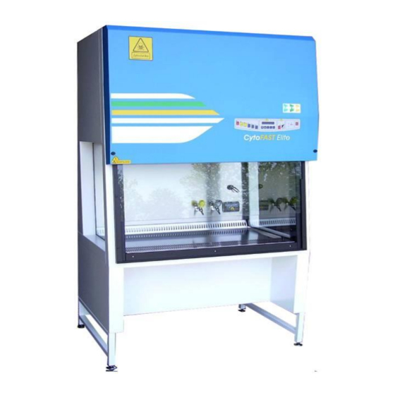
- Page 1 Commercial office: Via Merendi, 22 20010 Cornaredo (MI) Tel. +39.02.93.991.92 Fax. +39.02.93.991.608 E-mail: info@faster.dgroup.it OPERATING AND MAINTENANCE MANUAL CYTOFAST ELITE VERTICAL LAMINAR AIRFLOW CABINET FOR CYTOTOXIC DRUGS 00214EN - REV07 – 06/2016 (ORIGINAL INSTRUCTIOS)
-
Page 2: Table Of Contents
CONTENTS GENERAL .................................. 2 INSTALLATION ................................3 INSTRUCTIONS AND CHECKS ON DELIVERY ....................3 INSTALLATION REQUIREMENTS ........................3 ELECTRIC/GAS CONNECTIONS INSTALLATION OF THE WORK SURFACE ......... 5 OPERATION PRINCIPLES ............................7 OPERATION ................................8 SCOPE ................................8 CONTROL AND REGULATION SYSTEMS ....................... 8 REMOTE SIGNALS (OPTIONAL) ........................ -
Page 3: General
GENERAL Vertical laminar airflow benches with partial exhaust and protection barrier, the CYTOFAST ELITE cabinets, are designed to protect both the material to be manipulated from contamination and to protect the operator and the environment from microbial cytotoxic contamination hazards. The de-dusted, filtered and sterile air passing through the main HEPA filter ensures optimum airflow laminarity on the work surface, thanks to its even perforation and the frontal air barrier. -
Page 4: Installation
INSTALLATION INSTRUCTIONS AND CHECKS ON DELIVERY Considering the critical nature of the use of the CYTOFAST ELITE cabinet and the need to keep it in optimum condition, installation is very important. CYTOFAST ELITE Biohazard cabinets are positioned on a pallet, wrapped in an extensible film and contained in a package of multi-layer strapped cardboard. - Page 5 Thimble method example THIMBLE LEGENDA: 1. Exhaust air from the cabinet. 2. Air from the environment. 3. Bleed Air (100 200 m /h more than the exhaust air flow rate from the cabinet) to a dedicated exhaust fan (in the electronic board a voltage free contact is available –see electrical diagram- to check when Microbiological Safety Cabinet ventilation is ON).
-
Page 6: Celectric/Gas Connections And Installation Of The Work Surface
ELECTRIC/GAS CONNECTIONS and INSTALLATION OF THE WORK SURFACE The electrical connection of the CytoFAST Biohazard cabinet is made by connecting the power cable located on the upper of the right side of the cabinet to a suitable power point (see technical table) . When the cabinet is connected, the green light on the control panel switches on (see chapter 4E). - Page 7 Techincal Features Table Description Unit CytoFAST Elite 209 CytoFAST Elite 212 CytoFAST Elite 215 CytoFAST Elite 218 Overall Dimensions (L x H x P(*)) 1045x2345x860 1350x2345x860 1655x2345x860 1960x2345x860 Usefull dimensions (L x H x P) 899x740x580 1194x740x580 1499x740x580 1804x740x580 Maximum front aperture Working aperture Weight Noise level...
-
Page 8: Operation Principles
OPERATION PRINCIPLES The following are the working principles of the CYTOFAST ELITE-cabinet : the pressurized air pushed into the plenum of the main motor-fan passes through the absolute filter and then downwards, in laminar flow, into the working chamber (A). From here, through the slots of the work surface, having mixed with the external air (B) which enters the cabinet from the front opening, the air passes through the absolute filter placed under the work surface (C) and is sucked into the intake up channel situated at the rear of the working area (D). -
Page 9: Operation
OPERATION SCOPE The vertical laminar airflow cabinet CYTOFAST ELITE is manufactured in compliance with international standards for the protection of the material, the operator and the environment against biological (Class II) and cytotoxic hazards and is suitable for the manipulation of low- and middle-risk pathogenic agents. CONTROL AND REGULATION SYSTEMS The CYTOFAST ELITE cabinet is provided with an automatic regulation system to keep the airflow speed (0.4 m/sec) in the work chamber and the recycling air/extracted air ratio constant. -
Page 10: Cremote Signals (Optional)
REMOTE SIGNALS (OPTIONAL) The electronic control board can be improved adding the following optional features: Ventilation status (ON/OFF) It is possible to obtain a 12 Vdc output to connect a led light or alternatively a Normally Open voltage free contact to be connected to an external circuit. There are two different working possibilities: the signal starts when ventilation is turned ON and stops when ventilation is OFF. -
Page 11: Esymbols Of The Control Panel
SYMBOLS of the CONTROL PANEL List and description of all the symbols and controls of the control panel: 10 11 1 MAIN SWITCH: Position "0" in the "0" position, the green light of the mains voltage is on (3); the LCD displays the model name. - Page 12 7 LIGHT This switches on the fluorescent light; when enabled, the display shows "Light on". Switching on the fluorescent light automatically the U.V. lamp switches off. 8 UP/DOWN ARROWS Use the arrow keys to scroll the menu, to program changing parameters and to put in the password.
- Page 13 Operating Time: Shows the operating time of the cabinet from the moment when the main switch is positioned on "I" The LCD will display (for example) "WORK TIME=XXXXXh”. This value cannot be reset. 12 SPEED REDUCTION By pushing the corresponding red key the password (the same of start) is requested.
- Page 14 15 MUTE The red alarm LED lights up when an alarm condition occurs, which is shown also by the message appearing on the LCD. By pushing "MUTE" the alarm stops sounding. 16 UP/DOWN ARROWS Red safety button, working only in cabinets fitted with electrically operated, vertically sliding sash 00214EN Rev.07 –...
-
Page 15: Fmanagement And Programming Of Residual Lifetime
MANAGEMENT AND PROGRAMMING OF RESIDUAL LIFETIME Get access to operator menu when the cabinet is in stand-by pressing “ESC” [9] together with “UP arrow” [8] keys (password). The following diagram shows the organization of “OPERATOR MENU” By pressing “SET” [10] you can either go to the highlighted entry or confirm data entry while by pressing “ESC” [9] you go back to the beginning STAND-BY PASSWORD ESC+UP... - Page 16 TIMER (countdown): use "UP/DOWN arrow" keys [8] to scroll the operator menu select “TIMER SET UP.” and press "SET" [10] key; the display will show: TIMER SET UP SET UP hh:mm input the desired time and press SET [10] to confirm press ESC to exit the operator menu the display will show alternatively the countdown and the standard information when the countdown finish an audible signal will advise the operator.
- Page 17 UV PROGRAMMING: use "UP/DOWN arrow" keys [8] to scroll the operator menu select “UV PROGRAMMING” press "SET" [10]; and the display shows: UV LIGHTING LENGTH SET UP hh:mm input the desired time for the UV cycle and press SET [10] to confirm the display shows: .UV PROGRAMMING DATE &...
- Page 18 LANGUAGE SELECTION use "UP/DOWN arrow" keys [8] to scroll the operator menu select “LANGUAGE” and press "SET" [10] key; the display will show: LANGUAGE English With the “up and down arrow” keys select the desired language (Italian, English, French, German, Spanish).
- Page 19 DISPLAY OF HISTORICAL FILES use "UP/DOWN arrow" keys [8] to scroll the operator menu select “HISTORY VIEW” and press "SET" [10] key; the display will show: use "UP/DOWN arrow" keys to scroll through the list of the possible troubles happened . The list is in chronological order and contains up to 64 voices To conclude programming, press ESC”...
-
Page 20: Gdisposal Of Wastes And Contaminated Materials
4.G DISPOSAL OF WASTES AND CONTAMINATED MATERIALS DISPOSAL OF ELECTRIC AND ELECTRONIC DEVICES NFORMATION FOR UROPEAN NION USER This symbol on the device means that when it needs to be disposed, it must be handled separately from urban waste. At the moment of the disposal, contact the dealer, to receive information about the collect and disposal in accordance with the laws in force in the country. -
Page 21: Hergonomics
MATERIALS, WHICH THE CABINET IS MADE OF PARTS OF THE CABINET MATERIALS External structure Epoxy powder coated steel Inside work chamber AISI 304 stainless steel Work surface AISI 316L stainless steel Motor-fans Galvanized steel Filters Frame: in aluminium alloy Filtration bed: glass fibre Protection: Fe net/epoxy powder painted Gasket: polyurethane Keyboard... -
Page 22: Limitations
LIMITATIONS PRECAUTIONS for the correct use of the cabinet Listed below are the most important guidelines to be followed and the main substances to be avoided to ensure the correct use of the CYTOFAST ELITE cabinet: NEVER USE chlorine-based substances (e.g. sodium hypochlorite) as they are corrosive for the metal structure of the cabinet, and in particular for stainless steel parts. -
Page 23: Operating Procedures
OPERATING PROCEDURES PRELIMINARY CHECKS Before carrying out any type of work, the following conditions should be verified: that the cabinet power cable is connected to a power point at a suitable voltage and frequency as per instructions shown on the label stuck near the electric cable that all alarm lights are off that the work area inside the cabinet is free from materials used during the previous session. -
Page 24: Maintenance
ATTENTION: We remind you that the materials in the work area may be contaminated with pathogenic agents. Behave accordingly. MAINTENANCE INSTRUCTIONS FOR DAILY CLEANING OF CYTOFAST ELITE (by users) Clean the outside of the CYTOFAST ELITE cabinet, made of varnished iron-carbon sheet steel, using a damp cloth soaked in soapy water or some other commonly available products for varnished metal surfaces. -
Page 25: Bcleaning Of Glass
CLEANING OF GLASS for the internal cleaning of the glass proceed as follows (see also para 14A) : switch the cabinet off as per paragraph 6C. move the glass up in the position of maximum opening by pushing the proper button to have complete access to the back of the sash window open the control board [1] turning the locks [2] with the proper key ( –... - Page 26 If you use a FASTER formalin vaporizer follow this propcedure: 1. after filling the two containers of the vaporizer according to the above-said instructions, the vaporizer can be connected to the power point inside the cabinet. 2. set the timer at 6 hours. 3.
- Page 27 Picture 1 Picture 2. 00214EN Rev.07 – 06/2016...
-
Page 28: Dreplacement Of Hepa Filters (By Technical Assistance Personnel)
Post-fumigation cleaning Having performed fumigation, the manipulation of the filters is safe: however, this manipulation should be carried out by technicians wearing protective gloves and clothing. Before using the cabinet again any possible remains of the foregoing procedure of vaporization and relevant neutralization (which can show, for example, as white dust) must be removed from the work chamber. - Page 29 LAF Filter Open the front sash window completely by pressing the “arrow-up” button Switch off the cabinet and disconnect it from the mains Open the control board [1] turning the locks [2] with the proper key. Remove the internal panel [3] unscrewing the relevant fastening screws. 00214EN Rev.07 –...
- Page 30 Rotate the threaded bars [4] to release the HEPA filter [6]. (rear view) Remove the HEPA filter wearing PPD and put it in a hermetically sealed polythene bag. Place the additional gasket (if it is not already present) on the filter shoulder frame opposite the shoulder gasket of filter (already present).
- Page 31 Exhaust Filter 10. Rotate the fastening threaded bars [7] to lift down the plenum group [8] and to release the HEPA filter. (rear view) 11. Proceed as indicated in above 6, 7 and 8 points. 12. Lock the HEPA filter by rotating the fastening threaded bars [7]. 13.
- Page 32 ATTENTION: Gaskets should be of the closed-cell type and have no interstices in the joining points. Gaskets of EPDM, neoprene, hypalon, etc. may be replaced by CAF-type non-adhesive silicone. ATTENTION: the two main/exhaust HEPA filters should be replaced at the same time. Having replaced the filters, proceed with the calibration of the motor-fan speed.
-
Page 33: Ereplacement Of Motor-Fans (By Technical Assistance Personnel)
REPLACEMENT OF MOTOR-FANS (by technical assistance personnel) ATTENTION: before replacing the motor-fans, the cabinet must be decontaminated and a sterilization certificate must be issued to the technicians before starting operation (see par. 7D). For the safety of the personnel and the environment, the use of PVC gloves is recommended as well as the collection of the replaced materials in polyethylene bags. - Page 34 Remove the main motor-fan [11] including the side stirrup [12]. Position the new motor-fan after having mounted again the flow sensor group [15] and the relevant stirrup. Fasten the motor-fan with the relevant screws and reconnect electrical connectors. Proceed as indicated in the sub section "Replacement of HEPA filters", from 13 to 15 points. Replacement of exhaust motor-fan (only for CytoFAST Elite).
-
Page 35: Freplacement Of Fluorescent Lamps ( By Technical Assistance Personnel)
Remove the screws [20] of the exhaust fan [13] and the electrical connection. Place the new exhaust fan and set the wiring. Re-place the textile plenum REPLACEMENT OF FLUORESCENT LAMPS by technical assistance personnel) Lift down completely the front sash window Disconnect the mains power. -
Page 36: Hspare Parts List
SPARE PARTS LIST CODE DESCRIPTION CytoFAST Elite V20000003990 24V gas electro-valve V20000004010 Electro-valve connector V20000004510 Box IP-44 V20000004325 UNEL socket V20000006030 30 W/84 fluorescent lamp V20000006040 36 W/84 fluorescent lamp V20000006050 58 W/84 fluorescent lamp V20000006350 2x30W lamp-holder V20000006360 2x36W lamp-holder V20000006370 2x58W lamp-holder V20000006900... - Page 37 V50000100950 Main HEPA filter 730x287x400 (under the work surface) V50000100940 Main HEPA filter 530x287x400 (under the work surface) K60021230800 Left-hand side glass K60021231400 Right-hand side glass K60020930900 Frontal glass CytoFAST Elite 209 K60021230900 Frontal glass CytoFAST Elite 212 K60021530900 Frontal glass CytoFAST Elite 215 K60021830900 Frontal glass CytoFAST Elite 218 V20000006070...
-
Page 38: Troubleshooting - Probable Causes Of Malfunctions
TROUBLESHOOTING - PROBABLE CAUSES OF MALFUNCTIONS PROBLEM CAUSE REMEDY Cabinet does not work - Power outage upstream from the - Check the voltage input to the cabinet cabinet - Electronic board out of order - Replace PCB - Blown fuse(s) - Replace fuses Alarm: “front window open”... - Page 39 PROBLEM CAUSE REMEDY During work, an alarm sounds, the The exhaust fan is out of order above-mentioned problem “Alarms: low barrier laminar airflow works regularly, velocity”. and the velocity of the protective barrier is reduced by about 30%. IMPORTANT: if this problem Alarm: “barrier and exhaust fan"...
-
Page 40: Monitoring System
MONITORING SYSTEM ALARM OR ERROR MESSAGE DESCRIPTION Min. LAF Alarm Airflow speed in the work chamber under minimum threshold value Min. BARRIER Alarm Insufficient air suction from the front aperture, thus air speed in the exhaust channel under minimum threshold value LAF Triac Failure Too fast and uncontrollable main motor-fan (LAF) No encoder input LAF... -
Page 41: Transport, Packing And Storage Instructions
10 TRANSPORT, PACKING and STORAGE INSTRUCTIONS IMPORTANT: Disconnect the power and sterilize the unit before performing any of the following operations The following instructions are essential if the end user needs to transport, pack or store a cabinet after a period of routine use (e.g. - Page 42 Cardboard outer package of the following dimension: Cabinet model CytoFAST Elite 209 1130 2250 CytoFAST Elite 212 1450 2250 CytoFAST Elite 215 1750 2250 CytoFAST Elite 218 2050 2250 Steel straps and clips 00214EN Rev.07 – 06/2016...
- Page 43 During transport take care to maintain the package in a vertical position (i.e. the pallet at the bottom). The cabinet (with or without the package) must be kept in a place with the following environmental conditions: Min. temperature 0 °C Max.
-
Page 44: Additional Information
11 ADDITIONAL INFORMATION 11.A GUARANTEE The guarantee for vertical laminar air-flow cabinets is 24 months from date of invoice. In addition to those cases specifically indicated in Chapter 5 relating to improper use of the cabinet, the guarantee offered by Faster S.r.l., also excludes certain improper uses described in the instruction manual, of which the most important are listed again below : installation in a place which does not conform to the manufacturer’s recommendations wrong power voltage... -
Page 45: Diagrams
12 DIAGRAMS LEGENDA Ref. DESCIPTION Control board panel Control panel locks Internal panel LAF plenum tie-rod LAF plenum Main HEPA filter Screws fixing exhaust motor-fan EXHAUST plenum EXHAUST HEPA filter Screws fixing Main motor-fan Main motor-fan Stirrup main motor fan EXHAUST motor-fan Exhaust flow sensor Main flow sensor... -
Page 46: Adiagram For Maintenance Operations
12.A DIAGRAM FOR MAINTENANCE OPERATIONS 00214EN Rev.07 – 06/2016... - Page 47 Side view 00214EN Rev.07 – 06/2016...
-
Page 48: Bcytofast Elite Frontal And Side Diagram
12.B CYTOFAST ELITE FRONTAL and SIDE DIAGRAM CytoFAST Elite 1045 1350 1194 1655 1499 1960 1804 00214EN Rev.07 – 06/2016... - Page 49 00214EN Rev.07 – 06/2016...
-
Page 50: Assembly Of Support Table
13 ASSEMBLY of SUPPORT TABLE 14 ASSEMBY OF THE CABINET ON THE SUPPORTING STAND When the stand has been assembled the cabinet can be installed following this procedure: Check the correct levelling of the stand and in case adjust the height of the feet [3] Check the tightening of all the screws and the firmness of the stand Lift the cabinet with suitable equipment (for example a forklift) complying with the safety rules (the weight of the cabinet is shown in the “table of technical features”... - Page 51 00214EN Rev.07 – 06/2016...
-
Page 52: Safe Working Area Diagram
15 SAFE WORKING AREA DIAGRAM SAFE WORKING AREA SAFE WORKING AREA SAFE WORKING AREA SAFE WORKING AREA 00214EN Rev.07 – 06/2016... -
Page 53: Sensors List
16 SENSORS LIST SOFTWARE NAME PCB PLUG OF THE SENSOR DESCRIPTION GLASS POTENTIOMETER not used not used not used not used not used not used Card NBHG Card NBHG 00214EN Rev.07 – 06/2016... -
Page 54: Wiring Diagram
17 WIRING DIAGRAM 00214EN Rev.07 – 06/2016... - Page 55 00214EN Rev.07 – 06/2016...
- Page 56 00214EN Rev.07 – 06/2016...
- Page 57 00214EN Rev.07 – 06/2016...
-
Page 58: Declaration Of Conformity
18 DECLARATION OF CONFORMITY The undersigned legal representative of the company Faster S.r.l. hereby declares that the follow products: CytoFAST Elite are in compliance with the following directives: 2006/42/EC Directive of the European Parliament and of the Council on machinery 2014/30/UE Directive of the European Parliament and of the Council on the harmonization of the laws of the Member States relating to electromagnetic compatibility (recast)
Need help?
Do you have a question about the FASTER CYTOFAST ELITE Series and is the answer not in the manual?
Questions and answers