Table of Contents
Advertisement
Quick Links
Advertisement
Table of Contents

Subscribe to Our Youtube Channel
Summary of Contents for C-COM Satellite Systems iNetVu MP- 80
- Page 1 ® iNetVu Motorized (3-Axis) Man Pack – 80cm/100cm User Manual ® The iNetVu brand and logo are registered trademarks of C-COM Satellite Systems, Inc. © Copyright 2020 C-COM Satellite Systems, Inc. 1-877-iNetVu6 www.c-comsat.com Revision 3.0 January 22, 2020...
- Page 2 C-COM Satellite Systems Inc. Page 2 of 68 This page is intentionally left blank. ® iNetVu MOT- 80cm/100cm User Manual...
- Page 3 Proprietary Notice: This document contains information that is proprietary and confidential to C- COM Satellite Systems, Inc., and is intended for internal and or C-COM Satellite Systems Inc. authorized partners use only. No part of this document may be copied or reproduced in any way, without prior written permission of C-COM Satellite Systems, Inc.
-
Page 4: Table Of Contents
C-COM Satellite Systems Inc. Page 4 of 68 Table of Contents INTRODUCTION ........................5 ABOUT THIS MANUAL ......................5 SYSTEM OVERVIEW ....................... 5 PHYSICAL OUTLINE .......................6 SYSTEM WIRING DIAGRAM – NO MODEM (DVB RX ONLY) ..........8 SYSTEM WIRING DIAGRAM – MODEM ................9 CLEARANCE REQUIREMENT (DWG OUTDATED) ............ -
Page 5: Introduction
C-COM Satellite Systems Inc. Page 5 of 68 1. INTRODUCTION 1.1 ABOUT THIS MANUAL ® The iNetVu MP- 80/100 (ManPack) Motorized Pointing System, Installation and Operation are ® described in this manual. An electronic version of this manual is included on the iNetVu flash drive that came with your system. -
Page 6: Physical Outline
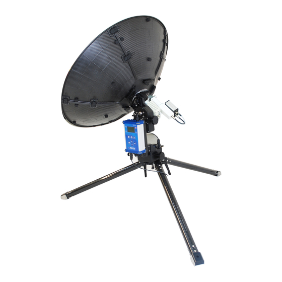
C-COM Satellite Systems Inc. Page 6 of 68 2. PHYSICAL OUTLINE Reflector Center Feed Module Tripod Leg Modem (Bracket) 8020 Controller Modem Power Supply Tripod Legs Tie Down Ring ® Fig. 2: iNetVu MP-80-MOT/100-MOT Front View ® iNetVu MOT- 80cm/100cm User Manual... - Page 7 C-COM Satellite Systems Inc. Page 7 of 68 NAV Module 8020 Controller Modem Tie Down Ring Eyebolt Ensure to use ballasts or anchors to secure down the antenna, failing to do so may result in equipment damage. ® Fig. 3:...
-
Page 8: System Wiring Diagram - No Modem (Dvb Rx Only)
C-COM Satellite Systems Inc. Page 8 of 68 3. SYSTEM WIRING DIAGRAM – NO MODEM (DVB RX ONLY) iNetVu™ MP-80 LAPTOP IP: 192.168.0.4 )))))))))))))) WIRELESS SSID 8020 + LAST 3 DIGITS OF SN# 8020 IP: 192.168.0.3 iNetVu™ DVB TUNER )))))))))))))))))))))))))))))))) -
Page 9: System Wiring Diagram - Modem
C-COM Satellite Systems Inc. Page 9 of 68 4. SYSTEM WIRING DIAGRAM – MODEM LAPTOP IP: 192.168.0.6 iNetVu™ MP-80 )))))))))))))) WIRELESS SSID 8020 + LAST 3 DIGITS 8020 IP: 10.10.10.1 OF SN# )))))))))))))))))))))))))))))))) iNetVu™ DVB TUNER 8020 IP: 192.168.0.2 RX IN... -
Page 10: Clearance Requirement (Dwg Outdated)
C-COM Satellite Systems Inc. Page 10 of 68 5. CLEARANCE REQUIREMENT (DWG OUTDATED) 5.1 MP-80-MOT CLEARANCE ® iNetVu MOT- 80cm/100cm User Manual... -
Page 11: Mp-100-Mot Clearance
C-COM Satellite Systems Inc. Page 11 of 68 5.2 MP-100-MOT CLEARANCE ® iNetVu MOT- 80cm/100cm User Manual... -
Page 12: Assembly/Disassembly
C-COM Satellite Systems Inc. Page 12 of 68 6. ASSEMBLY/DISASSEMBLY The assembly and disassembly of the MP-80-MOT and MP-100-MOT are identical. The only difference is the MP-100-MOT reflector consists of 7 Carbon Fiber segments instead of 5 on the MP-80-MOT. - Page 13 C-COM Satellite Systems Inc. Page 13 of 68 3) Tighten the handles while pressing down securing the tripod legs. Ensure the handles are pointing downwards as shown. Stabilize tripod using pegs, ballasts etc.. Note: Unit must be securely stabilized (via ballasts or pegs); failing to do so may compromise satellite lock and damage the unit.
- Page 14 C-COM Satellite Systems Inc. Page 14 of 68 5) Remove tube. 6) Place Turnbuckle on Eyebolt. Eyebolt Turnbuckle ® iNetVu MOT- 80cm/100cm User Manual...
- Page 15 C-COM Satellite Systems Inc. Page 15 of 68 7) Set Tripod over the Orange Screw and latch Turnbuckle. ® iNetVu MOT- 80cm/100cm User Manual...
- Page 16 C-COM Satellite Systems Inc. Page 16 of 68 8) Use the pegs to secure down the Tripod Legs; ensure the pegs are oriented as shown. 9) Set the case on its side and open flap. ® iNetVu MOT- 80cm/100cm User Manual...
- Page 17 C-COM Satellite Systems Inc. Page 17 of 68 10) Remove Elevation Center Section assembly from case; be careful handling, as the 8020 controller is attached. If Modem is attached in the bracket, be careful it does not slide out. 11) Loosen 2 Clamping Levers on the AZ base and make sure they are tilted forward. Line up the Corner Bracket notches from Center Section onto the tripod.
- Page 18 C-COM Satellite Systems Inc. Page 18 of 68 12) Make sure the Miniature Clamp Lever is loose to allow the Corner Bracket to slide under it. Miniature Clamp 13) Tighten the Miniature Clamp. ® iNetVu MOT- 80cm/100cm User Manual...
- Page 19 C-COM Satellite Systems Inc. Page 19 of 68 14) Turn and lock the Clamping Lever by pushing down. 15) Connect AZ motor cable from 8020 controller to AZ motor connector; note the orientation of the cable connector. The clip will snap out to lock connector in place.
- Page 20 C-COM Satellite Systems Inc. Page 20 of 68 16) Connect the following coax cables before applying power to the system. Note: All connectors to be tightened to 20 in-lbs ±5, if torque wrench available. Tighten the connector onto the female port. Once hand tightened, if a torque wrench is not available, a good rule of thumb is to wrench-tighten the connector an additional ¼...
- Page 21 C-COM Satellite Systems Inc. Page 21 of 68 Connect the other end of coax to BUC. d. Connect cable from DVB Module labelled “MODEM” to RF IN port on modem. e. Connect LAN cable. Ensure the coax cables on the DVB module are also tightened.
- Page 22 C-COM Satellite Systems Inc. Page 22 of 68 With Power adapter disconnected, connect Power cable to Controller. Push in to ensure connector snaps in and locks but DO NOT plug the cable into the power source just yet. Locking Clip 18) Flip the case over so it’s flat on its back.
- Page 23 C-COM Satellite Systems Inc. Page 23 of 68 19) Open the case; this top compartment contains the Reflector Petals, Feed, and Center Hub. 20) Remove Center Hub from case. ® iNetVu MOT- 80cm/100cm User Manual...
- Page 24 C-COM Satellite Systems Inc. Page 24 of 68 21) Install Center Hub and lock into place using the Lock Levers. Ensure the Hub plate and EL Mounting Arm Bracket are flush against each other. 22) Connect Polarization motor connector and ensure connecting locking clip snaps out.
- Page 25 C-COM Satellite Systems Inc. Page 25 of 68 23) Connect external power adapter from 8020 Controller to power outlet. 24) Turn on 8020 Controller. ® iNetVu MOT- 80cm/100cm User Manual...
- Page 26 C-COM Satellite Systems Inc. Page 26 of 68 25) Install reflector segments (petals). Latch 2 segments at a time. Do not latch the last 2 segments until all segments have been installed. MP-80 will have 5 reflector segments while the MP-100 has 7 reflector segments.
- Page 27 C-COM Satellite Systems Inc. Page 27 of 68 27) Lock the latches by rotating the locking mechanism counter clockwise (CCW) or clockwise (CW) so the tab is perpendicular to the latch. ® iNetVu MOT- 80cm/100cm User Manual...
- Page 28 C-COM Satellite Systems Inc. Page 28 of 68 28) Remove Feed from case and install on hub. Turn the Feed clockwise until it locks into place. ® iNetVu MOT- 80cm/100cm User Manual...
- Page 29 C-COM Satellite Systems Inc. Page 29 of 68 29) *Calibrate Compass – go to Menu, the COMPASS option should be highlighted (selected). Note: This task is required if the system was received without an LNB installed. It Should be performed only once when the system is first set up or if the hardware is replaced.
- Page 30 C-COM Satellite Systems Inc. Page 30 of 68 33) Manpack is now setup and ready to use. 34) Press FIND SAT button or login to WEB GUI Interface to operate via the WEB, see section 6 of this Manual for WEB Interface.
-
Page 31: Disassembly Procedure
C-COM Satellite Systems Inc. Page 31 of 68 6.2 DISASSEMBLY PROCEDURE 1) Press Home (Stow) button on 8020 Controller. 2) Power off 8020 Controller once the Homing routine finishes. 3) Disconnect RX cable from LNB. 4) Disconnect TX cable from BUC. - Page 32 C-COM Satellite Systems Inc. Page 32 of 68 6) Remove Center Feed, turn Counter clockwise ¼ turn and lift. Place in case. Place Feed in the case. 7) Turn the locking mechanism so the tabs are parallel to the latches.
- Page 33 C-COM Satellite Systems Inc. Page 33 of 68 8) Unlatch the reflector segments starting at the top of the dish. 9) Remove segments, wiggle the center top segment that was un-latched, so it separates from the rest. (Once one is removed, the rest will easily come apart) and place in the case.
- Page 34 C-COM Satellite Systems Inc. Page 34 of 68 10) Disconnect Polarization cable from 8020 Controller. ® iNetVu MOT- 80cm/100cm User Manual...
- Page 35 C-COM Satellite Systems Inc. Page 35 of 68 11) Release 3 Clamp Levers on Center Hub and remove in the direction of arrows. ® iNetVu MOT- 80cm/100cm User Manual...
- Page 36 C-COM Satellite Systems Inc. Page 36 of 68 12) Rotate OMT with LNB so that the OMT is resting on the hard stop. 13) Place Center Hub in the case. Align edge so it is straight as shown. ® iNetVu...
- Page 37 C-COM Satellite Systems Inc. Page 37 of 68 14) Close case. 15) Turn case on its side and open flap. ® iNetVu MOT- 80cm/100cm User Manual...
- Page 38 C-COM Satellite Systems Inc. Page 38 of 68 16) Unplug external power cable and put Power Supply in case. 17) Remove RF OUT Coax cable from modem and place in case (smaller pouch). ® iNetVu MOT- 80cm/100cm User Manual...
- Page 39 C-COM Satellite Systems Inc. Page 39 of 68 18) Disconnect AZ Power cable from AZ gear box. Press clip in while disengaging. 19) Place attached weather cap on AZ Gear Box connector and release the Miniature Clamp Lever. ® iNetVu...
- Page 40 C-COM Satellite Systems Inc. Page 40 of 68 20) Release AZ/EL Clamp Levers and rotate until the Elevation assemble can easily slide out. 21) Place Elevation assembly in the case. ® iNetVu MOT- 80cm/100cm User Manual...
- Page 41 C-COM Satellite Systems Inc. Page 41 of 68 22) Release Tripod Locking Handles and fold legs. The Handles can be locked again after folding the legs to secure them in closed position. ® iNetVu MOT- 80cm/100cm User Manual...
- Page 42 C-COM Satellite Systems Inc. Page 42 of 68 23) Place Tripod in the case and close flap. 24) Close the case and fasten zipper. Man-Pack is now ready for travel. ® iNetVu MOT- 80cm/100cm User Manual...
-
Page 43: Pointing Antenna With Onboard 8020 Controller
C-COM Satellite Systems Inc. Page 43 of 68 7. POINTING ANTENNA WITH ONBOARD 8020 CONTROLLER ® The iNetVu 8020 Controller is attached to the Elevation center assembly on the motorized ® iNetVu MP-80 or MP-100 Manpack Antennas. The basic button functions are described below. -
Page 44: Main Screen
C-COM Satellite Systems Inc. Page 44 of 68 7.1 MAIN SCREEN a. Status (Stat), Elevation Angle (El), Azimuth Angle (Az), dB signal and Receive Polarity and Angle (RX) for the selected carrier. b. Scroll Down - GPS Screen. ® iNetVu... - Page 45 C-COM Satellite Systems Inc. Page 45 of 68 c. Scroll Down to Carrier List. Press ENTER, scroll up and down through the list. d. Select the Manual Carrier from the list. This will enable additional fields. Note: Only the Manual carrier option allows the user to modify the carrier from the 8020 front panel ®...
- Page 46 C-COM Satellite Systems Inc. Page 46 of 68 e. Scroll down to Sat Selection, select the Satellite Longitude ( by pressing ENTER button), this will allow you to change/modify Satellite and RX Polarity. Press Enter to continue. f. Scroll down to DVB Select, this screen allows configuration of Frequency and Symbol Rate.
-
Page 47: Menu Features And System Calibration
C-COM Satellite Systems Inc. Page 47 of 68 7.2 MENU FEATURES AND SYSTEM CALIBRATION 1. Power on 8020 Controller. The iNetVu logo will display during bootup. ® iNetVu MOT- 80cm/100cm User Manual... - Page 48 C-COM Satellite Systems Inc. Page 48 of 68 2. The 8020 will display Elevation (EL) angle, Azimuth (AZ) angle and Polarization (PL) Polarity for the currently configured satellite. If the correct satellite is already set, press FIND SAT button, otherwise continue with steps.
- Page 49 C-COM Satellite Systems Inc. Page 49 of 68 3. Press Menu button to access features. Compass – Calibrates the compass – Press Enter once highlighted and follow screen prompts. RF Level – Calibrates values from LNB. This is necessary every time a new LNB is used or changed- Press Enter once highlighted on the screen.
- Page 50 C-COM Satellite Systems Inc. Page 50 of 68 4. Calibrate the system on first use, or when ever you expect the compass reading to be off or incorrect. The system will auto calibrate if it fails to lock on satellite.
- Page 51 C-COM Satellite Systems Inc. Page 51 of 68 5. It is Recommended to do RF Level on the system when a new LNB is installed for first time. a. Press MENU to access feature. b. Select RF Level and press ENTER. This will take RF samples and display a “Samples Completed”...
- Page 52 C-COM Satellite Systems Inc. Page 52 of 68 b. The first carrier in the satellite GEO list should now be highlighted. Press the DOWN or UP arrow to toggle through the list. Press ENTER on the desired carrier to select it.
- Page 53 C-COM Satellite Systems Inc. Page 53 of 68 d. Each carrier will also have a Threshold (minimum signal detection) , RX Polarity and SKO (POL Offset) parameter. Only the RX Polarity is configurable from the front panel and only under MANUAL carrier option.
- Page 54 C-COM Satellite Systems Inc. Page 54 of 68 9. Once the carrier is set the press FIND SAT. 10. The system will scan, determine and set the Polarization angle for the configured satellite and display it on the 8020 Controller screen under RX-V or RX-H.
-
Page 55: Antenna Web Interface
C-COM Satellite Systems Inc. Page 55 of 68 8. ANTENNA WEB INTERFACE The 8020 Controller WEB Interface allows the user to monitor real-time system parameters such as Signal Strength, GPS Coordinates, Real and Target angles for the system axis, as well as allowing the user the capability of manually moving the antenna just to mention a few of the available functions. -
Page 56: Controls
C-COM Satellite Systems Inc. Page 56 of 68 8.2 CONTROLS The Web Interface Automatic Controls window allows the user to monitor system operations and perform satellite search (FIND SATELLITE) as well as stowing/homing (PREP) the system. The Configuration and About information can also be accessed from the Controls by clicking on the menu option. -
Page 57: Automatic
C-COM Satellite Systems Inc. Page 57 of 68 The Controls screen has 4 sub menu items: AUTOMATIC, MANUAL, MAINTENANCE and DEMO. 8.2.1 AUTOMATIC The system will automatically move on the requested commands (FIND SATELLITE OR PREP ANNTENNA) with the click of a button. -
Page 58: Maintenance
C-COM Satellite Systems Inc. Page 58 of 68 8.2.3 MAINTENANCE The Maintenance menu provides two features: RESET CONTROLLER AND DOWNLOAD LOG FILE. RESET CONTROLLER Restarts controller. DOWNLOAD LOG FILE Downloads the log data from the 8020 Controller and displays it in a browser tab. -
Page 59: Carriers
C-COM Satellite Systems Inc. Page 59 of 68 8.3 CARRIERS Users have the ability to configure (ADD CARRIER) and save 256 carriers with their Satellite Longitude, Frequency, Symbol Rate and other configurable parameters. Each Carrier can have different configurable parameters settings independent of one another. -
Page 60: Carrier Configuration
C-COM Satellite Systems Inc. Page 60 of 68 8.3.1 CARRIER CONFIGURATION 1 – CARRIER SELECTION Displays all the carriers in the list and allows operator to select the desired carrier. Carriers that are added or removed will be reflected in this list. -
Page 61: Carrier Buttons
C-COM Satellite Systems Inc. Page 61 of 68 7 – SKEW OFFSET The Carrier Skew is any known Skew on the target satellite. The Carrier Skew is used to adjust the difference between the satellite polarity and physical polarity on the mount. The allowed Skew range is from -50... - Page 62 C-COM Satellite Systems Inc. Page 62 of 68 NEXT CARRIER Displays the next carrier in the list and all the carrier configured parameters. ADD CARRIER A carrier can be added by clicking the ADD CARRIER button. After filling out all the required fields/parameters click on the SAVE TO CONTROLLER button to add the carrier to the carrier list.
-
Page 63: Configuration (Config)
C-COM Satellite Systems Inc. Page 63 of 68 8.4 CONFIGURATION CONFIG The Config window allows the user/operator to configure search parameters. The operator can enable the compass to calibrate automatically, configure the satellite Search Method, Controller IP address etc... and as well override certain parameters. Configuration changes are saved only after “SAVE SETTINGS”... -
Page 64: Search Options
C-COM Satellite Systems Inc. Page 64 of 68 8.4.1 SEARCH OPTIONS AUTO COMPASS CALIBRATION System will automatically run the Compass Calibration routine if system fails to lock on satellite signal. The calibration is accomplished by rotation of 180 degrees on the Azimuth axis. -
Page 65: Network Interface
C-COM Satellite Systems Inc. Page 65 of 68 LATITUDE ® This field represents the Latitudinal GPS coordinates of the iNetVu system for OVERRIDE mode only. LONGITUDE ® This field represents the Longitudinal GPS coordinates of the iNetVu system OVERRIDE mode only. - Page 66 C-COM Satellite Systems Inc. Page 66 of 68 MANUAL IP – Allows user to manual set the LAN IP for the 8020 controller. ® AUTO IP - The iNetVu 8020 Controller could obtain a dynamic IP address from a DHCP Server (i.e.
-
Page 67: About
C-COM Satellite Systems Inc. Page 67 of 68 8.5 ABOUT Displays information to the user, such as the 8020 Software version, Serial number, MAC Address, and the current Satellite Longitude. ® iNetVu MOT- 80cm/100cm User Manual... -
Page 68: Conformity Letter
C-COM Satellite Systems Inc. Page 68 of 68 9. CONFORMITY LETTER Declaration of Conformity Application of Council Directive EMC Directive 2014/30/EU Low Voltage Directive 2014/35/EU Standards to which Conformity is Declared CISPR 32:2015/EN55032 2012, Class A VCCI-CISPR 32:2016 - Emission...
Need help?
Do you have a question about the iNetVu MP- 80 and is the answer not in the manual?
Questions and answers