Table of Contents
Advertisement
Quick Links
Advertisement
Table of Contents

Summary of Contents for AIS PIXIE RP10 Series
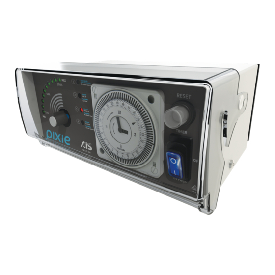
- Page 1 THIS MICRO CHLORINE GENERATOR CREATES A TOTALLY REJUVENATING SPA AND PLUNGE POOL EXPERIENCE. Universal Model This manual is for: PIXIE RP10 MODELS ERP10H (Euro model) RP10TH (Universal model with timer) RP10QTH (With battery backup) INSTRUCTION MANUAL...
- Page 2 • Australian Innovative Systems Pty Ltd (AIS Water) reserves the right to change the specifi cations of the hardware and software described herein at any time without prior notice.
- Page 3 CHLORINE GENERATOR FUNCTIONS 2 3 4 Fig. 1 1. Status Light 1 – High Salt (Note: When chlorine output lights are off and ‘power on (light 3)’ and ‘cell off (light 2)’ If the light is on see Troubleshooting guide, lights are on, chlorine production is in page 17.
-
Page 4: Water Balance
THE PIXIE™ SALTWATER CHLORINATION SYSTEM Congratulations on your choice of a Pixie™ saltwater chlorinator system for your swimming pool. The Pixie™ saltwater chlorinator you have purchased is designed for easy and simplistic operation and maintenance. By following these instructions, you are assured years of trouble- free operation. - Page 5 CHLORINE GENERATOR INSTALLATION FITTING THE CHLORINATOR CELL HOUSING The Pixie™ cell housing must be plumbed into the return line of the pool fi lter system after the fi lter and any diversion valves. Please refer to the installation diagram for the correct method of installation (Fig.
-
Page 6: Installing The Power Supply
INSTALLING THE POWER SUPPLY The Pixie™ power supply should be mounted on a wall using the fi ttings supplied. We recommend using the supplied mounting template provided to affi x the wall plugs and mounting screws. The power supply should then slip into the keyhole slots on the rear of the unit. It is preferable that the power supply is mounted in a location where it is protected from accidental water spray and inclement weather. - Page 7 RAISING THE SALINITY OF A NEW POOL For best results the salt concentration in the pool water is required to be within an average range of approximately 4,000 to 5,500 parts per million (ppm). These fi gures are temperature dependant. In summertime, as water temperatures rise, salt levels may require slight reduction while in wintertime the reverse may be true to allow optimum performance of your unit.
- Page 8 GENERAL CHLORINATOR OPERATION Before switching on your Pixie™ saltwater chlorination system please ensure that you have added the correct amount of pool salt, it has fully dissolved and is distributed throughout the pool water. Ensure that the base pool chemistry is at the recommended levels and the pool water is clean and crystal clear (see Water Balance Section).
- Page 9 CHLORINATOR RUNNING TIMES Chlorinator running times will vary from pool to pool and are dependent upon the situation they are installed into, pool size and the overall usage of the pool in general. We recommend 2 hours break for every 4 hours of operation to prolong life of the power supply. The chlorinator should not be run for more than 10 hours continuously.
- Page 10 CHLORINE OUTPUT INDICATOR (FIG. 1, ITEM 6) Your power supply is fi tted with ten green indicator lights set in an arc shaped formation. During operation of your chlorinator these lights will illuminate relevant to the degree at which the chlorine controls have been adjusted. Working in conjunction with the chlorine controller you can increase or decrease chlorine output to suit your pool’s requirements.
- Page 11 STEADY STEADY SALT HIGHER SALT HIGHER Cell o Cell o FLASHING FLASHING THAN NECESSARY THAN NECESSARY Salt low Salt low No action required No action required STEADY STEADY STEADY STEADY Power on Power on Cell o Cell o FLASHING FLASHING FLASHING FLASHING No Water Flow...
-
Page 12: Circuit Breaker
CIRCUIT BREAKER The circuit breaker is designed to trip out in the event of a power surge or power overload. When tripped the centre button will pop out shutting down the unit to prevent damage. To reset, depress circuit breaker until a click is heard. ON/OFF SWITCH –... - Page 13 Start and stop times are set by pushing the black pins out for on and inward for off. For example, to turn the chlorinator on between 6 pm and 10 pm, push all the pins outwards between 18 and 22. The remainder of the pins should be pushed inwards. With the elements pushed outwards the timer will turn your equipment on when they reach the black indicators.
-
Page 14: Maintenance
MAINTENANCE ELECTRODE INSPECTION: Pixie™ has a reverse polarity feature which reduces electrode cleaning. Regular inspection of the electrode is recommended. ELECTRODE REMOVAL: Ensure the power to the chlorine generator is switched off . Step 1 Step 2 Step 3 Step 1. Unplug the electrode lead from the electrode. Step 2. -
Page 15: Electrode Cleaning
ELECTRODE CLEANING: Mix up a solution of 1-part hydrochloric acid to 8 parts water. Submerse the electrode in this solution. Do not submerse brass terminals. CAUTION: • When working with acid the use of eye protection, respirator, and rubber gloves are strongly recommended. -
Page 16: Troubleshooting Guide
TROUBLESHOOTING GUIDE PROBLEM REASON SOLUTION There are no lights on the There is no mains power Unplug the chlorine chlorine generator and the generator from the power pump is not running and test power outlet with another known working appliance The time clock is in a designated off period, Switch to BYPASS to... - Page 17 Have the salinity level or flashing tested by pool professional and decrease to 5,500 if necesssary Contact dealer or AIS Chlorine generator is faulty Water. The low salinity light is on Water salinity is too low Have the salinity level tested...
-
Page 18: Technical Specifications
TECHNICAL SPECIFICATIONS Chlorine output 10 g/hr (grams of chlorine gas equivalent per hour) Input voltage (V) 220-240v, 50 hz Input current (A) 0.4 amps Output voltage (V) Output current (A) 6.5 amps Unit cooling Convection, via external heatsink No fl ow protection Automatic water fl ow sensing Water fl... -
Page 19: Warranty
All chlorine generators are fully tested prior to being packed. If within 48 months of purchase a problem occurs due to faulty workmanship or components, AIS Water will (at their discretion) repair or replace the chlorine generator. - Page 20 Head Office +61 7 3396 5222 51 Millennium Place, Tingalpa, Queensland 4173 Australia Email: info@aiswater.com.au Facsimile +61 7 3393 3441 WARRANTY HOTLINE 1800 676 076 (Australia wide) Scan any AIS Water logo to learn “Why aiswater.com.au Enhancing life choose AIS?”...
Need help?
Do you have a question about the PIXIE RP10 Series and is the answer not in the manual?
Questions and answers