Table of Contents
Advertisement
Quick Links
®
Installation and Operation Manual
16 x 1
Sixteen Input, Single Output Stereo Switcher/Router
Firmware Version 060201
Manual Update: 2/10/2004
Due to the dynamic nature of product design, the information contained in this
document is subject to change without notice. Broadcast Tools, Inc., assumes no
responsibility for errors and/or omissions contained in this document. Revisions
of this information or new editions may be issued to incorporate such changes.
Broadcast Tools® is a registered trademark of Broadcast Tools, Inc.
Copyright, 1989 - 2005 by Broadcast Tools, Inc. All rights reserved.
No part of this document may be reproduced or distributed without permission.
Visit www.broadcasttools.com for important product update information.
Advertisement
Table of Contents

Summary of Contents for Broadcast Tools SS 16.1
- Page 1 Manual Update: 2/10/2004 Due to the dynamic nature of product design, the information contained in this document is subject to change without notice. Broadcast Tools, Inc., assumes no responsibility for errors and/or omissions contained in this document. Revisions of this information or new editions may be issued to incorporate such changes.
-
Page 2: Table Of Contents
SS 16.1 Installation and Operation Manual Table of Contents Section Title Page # Introduction ..........3 Safety Information . -
Page 3: Introduction
If you have any questions regarding your product or you need assistance, please con- NOTE: tact your distributor from whom you purchased this equipment. This manual should be If you would like more information about Broadcast Tools® products, you may read thoroughly before reach us at: installation and operation. -
Page 4: Product Description
SS 16.1 Installation and Operation Manual PRODUCT DESCRIPTION The 16x1 passively switches or routes any one of 16 stereo inputs to one stereo out- put or vise-versa through gold contact relays. The passive nature of the switching allows for any input level and impedance to be used. Inputs may be balanced or unbalanced, while output levels, impedance, distortion, noise and balancing will match that of the selected input. -
Page 5: Front Panel Description
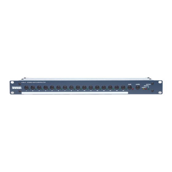
SS 16.1 Installation and Operation Manual FRONT PANEL DESCRIPTION LEDs: LED indicators, which will illuminate when the desired channel is selected. The Pwr/Ser LED displays valid power and serial data activity. The mute LED denotes when audio is off. The activity LED is lit when audio is present at the output. -
Page 6: Installation Guidelines
SS 16.1 Installation and Operation Manual INSTALLATION GUIDELINES Installation of the 16 x 1 in high RF environments should be performed with care. Shielded cable is suggested for all control, audio inputs and outputs. All shields should be tied to the EGND terminals. The station ground should be connected to the chassis ground screw located on the far right side of the 16 x 1 as viewed from the rear. -
Page 7: Step 3
SS 16.1 Installation and Operation Manual STEP 3: BENCH TEST and OPTIONS Place each unit on a workspace and connect power to the unit. Check to see if LED #1 (Switch 1) and the Pwr/Ser LED are lit (Source one is the power-up factory default). -
Page 8: Steps 4-7
SS 16.1 Installation and Operation Manual STEP 4: MOUNTING Mount the unit in a rack or desktop, allowing adequate airflow for cooling. STEP 5: CONNECT YOUR EQUIPMENT The 16 x 1 interfaces to your equipment (sources and loads) through the rear panel pluggable screw terminals. -
Page 9: Remote Control Connector Pinouts
SS 16.1 Installation and Operation Manual Command Examples without ID: *b<cr>Turn ON bypass *u<cr>Bring up set up menu. Menu: The menu allows the selection of stepping time and the selection of the last channel in the step. The stepping time can be between 1 and 999 seconds. The last channel step is selec- table from channels 1 through 16. - Page 10 SS 16.1 Installation and Operation Manual INSTALLATION GUIDELINES Remote Control Connector Pinouts: Control Continued J3 Remote Status Pin Numbers: 20 Status number 1 21 Status number 2 22 Status number 3 23 Status number 4 24 Status number 5 25 Status number 6...
-
Page 11: 16 X 1 Specifications
SS 16.1 Installation and Operation Manual BROADCAST TOOLS ® 16 X 1 SPECIFICATIONS Inputs/Outputs: Any input level and impedance can be used. Inputs may be balanced or unbalanced. Output levels, impedance, distortion, noise and balancing will match that of the selected input. -
Page 12: Warranty
If Broadcast Tools is notified, in writing, of a failure of any item manufactured by Broadcast Tools to conform to the foregoing Limited Warranty within one (1) year following the date of the Buyer’s acquisition of the item, and if the item is returned to Broadcast Tools in accordance with Broadcast Tools’...


Need help?
Do you have a question about the SS 16.1 and is the answer not in the manual?
Questions and answers