
Summary of Contents for Connect Systems CS-BFD
- Page 1 CS-BFD USERS MANUAL Connect Systems Inc 5321 Derry Ave., Suite B Agoura Hills, CA 91301 Copyright 2019...
- Page 2 INTRODUCTION The CS-BFD is the first in a set of products that allows the HAM to increase the functionality of their existing radios. The firmware and the hardware design will be available to allow the resourceful HAM to modify the product to exactly meet their needs and desires as well as the ability to be modified to work with other radios.
-
Page 3: Mechanical Parameters
MECHANICAL PARAMETERS Weight: 25 Ounces Dimensions: 7 ¾ x 6 ¾ x 1 ¼ Screen Diagonal Size: 7” Active Screen Size 6 x 3 ½ JUMPERS... - Page 4 JP1 is used to determine the source of its power. If the jumper is between the center pin and the pin closest to the top of the display, then the power is derived from the radio. If the jumper is between the center pin and the bottom of the display, then the power is derived from an external power supply.
- Page 5 REAR OF THE CS-BFD Notice the four holes on the back are made to fit any AMPS compatible device. That will allow you to buy compatible mounting devices from RAM MOUNTS and others...
-
Page 6: Updating The Firmware
UPDATING THE FIRMWARE We are going to continue updating this product for a long time to add new features, fix problems, and add the ability to add new radios. Updating the firmware takes just a few seconds after the Dfuse program is installed. Updating can normally be done by pressing the P1 and P4 keys at the same time while power is applied. - Page 7 CS800D KEYS VERSES CS-BFD KEY CS800D CS-BFD LEFT ROTARY SWITCH CW LEFT ROTARY SWITCH CCW PRESS LEFT ROTARY SWITCH RIGHT ROTARY SWITCH Note: There is no equivalent of P5 and P6 long press. It is suggested to use the microphone buttons for that purpose.
- Page 8 ICONS DESCRIPTION Digital Monitor Message Encryption Alert Tone Call Type Talk Around Scan ICONS DESCRIPTION...
- Page 9 RSSI Last Called...
- Page 10 Setting the parameters back to factory default If you have problems reading the screen or you want to erase the favorites you already put in, pressing the P3 key as you turn on the power will set everything back to factory default.
- Page 11 (4) Press the power switch on the CS-BFD for about six seconds. In a few seconds the display will light up and you are now ready to use the CS-BFD. If the radio turns off after you released the power switch, you did not press the power switch long enough.
- Page 12 OPERATION OF THE CS-BFD When you first turn on the CS-BFD, you will get the following splash screen:...
- Page 13 Followed by this screen By comparison, if you have the standard CS-800D with the small screen, you will get the following when you first turn on...
- Page 14 If you press the PTT, then you will get the following screen:...
- Page 15 If you are receiving a QSO you get the following screen:...
- Page 16 If you want to see the last called, you press the ICON to the left of the P1 soft key and you get:...
-
Page 17: Advanced Features
ADVANCED FEATURES Pressing the rotary switch on the right will bring up the following screen: The up and down arrow on the touch screen or P2 or P3 will select which feature you want to select. The solid circle on the touch screen or P4 will select that feature that is highlighted. - Page 18 Advanced Features Pressing the Advanced Features menu gives the following screen:...
- Page 19 Advanced Features 1. Enhanced Monitor Mode Your display will show graphically the different groups being received and the length of time that group has been active. 2. Enhanced Channel Entry From a single screen, able to enter all the parameters necessary for creating a temporary channel.
- Page 20 Color settings The Color setting will allow you to change the default colors on the different screens. The program assumes a fixed palette of colors. If you do not like the selection it is possible to completely redefine the color selection in the palette.
- Page 21 The design of this product is based on reverse engineering the operation of the radio attached to the CS-BFD. Different packets are sent from the radio dependent on the keys the user presses and what is happening with the radio. It is possible we never seen a particular event happen and that event gives us a packet we have never seen before.
-
Page 22: Color Setting
COLOR SETTING If the color setting is selected, you will get a screen as shown below. You can now select what feature of the screen you want to change. As an example, I will show how to change the text to white and the text background to black. - Page 23 You get the screen as shown below. Now use the left arrow of P2 or the right arrow or P3 to select the color of the text font. In this case we want to select white. Notice that when the arrow key is moved to the left or right, the active color is show with a blue outline When you get the appropriate color, press the circle with your finger or the P4 key.
- Page 24 Now press the circle or the P4 key and notice that the Text Font went from black to white.
- Page 25 Press the red X or the P1 key and the screen will return to the previous screen as shown below.
- Page 26 Press the red X or the P1 key one more time and you will get the following screen:...
- Page 27 Press the Yes or P4 key and you are finished. Pressing the rotary switch on the right will return you to the main screen as shown below.
- Page 28 Button Names This is a future feature where the functions of the button that you selected in the CPS when programming the radio will be displayed on the screen.
- Page 29 Radio Type This feature is used to select which is the active radio. At the current time the only choices is CS800D UART 1 FT857D UART 1 FT857D UART 2 is not currently available.
-
Page 30: Error Log
ERROR LOG There are a significant number of traps in the firmware to look for problems that should never happen. The error log records the information and allows the user to see those. The customer should take a photo of those errors and send it to the factory to allow us to make the firmware better. - Page 31 EVENT LOG To help with diagnostics, especially when there is a problem, we provide a screen that shows the major transaction the CS-BFD processed. We might ask you to take a photo of this screen to help resolve unknown issues.
- Page 32 DIAGNOSTICS To help with hardware problems, the CS-BFD has a complete set of hardware diagnostic test that should isolate any problems.
- Page 33 If all the hardware diagnostics test passed, you get the following screen. In order to have all test passed, it is necessary to make shorting plugs for USB1, USB2, and the UART port.
- Page 34 This error indicates there is an unknown packet and the user should take a photo of this screen as well as the event log screen and the unknown packet screen and e- mail it to connect systems so we can fix the problem.
- Page 35 ADVANCED FEATURES Pressing the rotary switch on the right will bring up the following screen The up and down arrow on the touch screen or P2 or P3 or the right rotary switch will select which feature you want to select. The solid circle on the touch screen or P4 will select that feature that is highlighted.
- Page 36 The up and down arrow on the touch screen or P2 or P3 or the right rotary switch will select which feature you want to select. The solid circle on the touch screen or P4 will select that feature that is highlighted.
- Page 37 This feature will allow you to quickly select up to 1 of 16 preprogrammed zones. The setup of this feature is done entirely through the CS-BFD without the need for the CPS and loading a code plug. When selecting the zone, you are always starting with channel 1 of that zone.
- Page 38 Spectrum View This feature will allow you to see the amplitude of the signal over a frequency range. This is what is known as a spectrum Analyzer.
- Page 39 Enhanced Monitor Mode If you let the CS-BFD monitor a repeater for a length of time, the CS-BFD will gather the activity on the channel and display it in graphical form as shown in the above screen. If you want to see the details of the various groups, press the right arrow key or P3 and you will get the display shown on the next page.
- Page 40 Notice the display shows the name of the talk group, how long the channel was occupied, and the number of times someone tried to use that talk group.
- Page 41 Enhanced Channel Entry To move between parameters in this and other menus, the box around the parameter must be blue. When it is red it means you can change the value of the parameter. The change the active parameter position, use the right encoder, the up and down arrow keys, or P2 and P3.
- Page 42 Rx frequency This selects the Rx frequency either by turning the right encoder switch or a direct entry by using the DTMF keypad on the microphone. Pressing the enter key twice exits from this menu. Step This is the step size when adjusting the Rx frequency. The possible entries are: 10 Hz 20 Hz...
- Page 43 Call Type This is a DMR only parameter and gives you a choice of Private, Group, or All. Color This is a DMR only parameter and allows you to select the color code from 0 through 15. Slot This is a DMR only parameter and allows you to select Slot 1 or Slot 2 Contact id This is a DMR only parameter and allows you to enter...
- Page 44 DCS decode This is an Analog only parameter and allows all standard values between 023 and 754. Once you finish changing the parameters as necessary, press the Activate button twice and you will get the following screen: THIS SHOULD BE THE TEMP DCH CHANNEL SCREEN Notice the screen name is “Temp”...
- Page 45 Enhanced Scanning Mode The purpose of the enhanced scanning mode is to look for activity between two frequencies. When you get into the Enhanced Scan mode you get the following screen: To change the parameters associated with this function, scroll to the appropriate parameter you want to change and then press the P4 key.
- Page 46 Now change the parameter by entering it from the microphone followed by a P4 or you can sometimes using the encoder on the right side to increment or decrement the value. Once you change the value as shown below, just use the up and down arrows to move to the next parameter.
- Page 47 VFO Mode The purpose of the VFO mode is to allow the user to manually scan the different frequencies to find an active channel. This feature makes more sense in Analog because digital channels usually predetermined in advance and you should only look for specific channels.
- Page 48 If you were going to get a digital VFO channel you will get the following: To change the parameters, use the up and down arrow to select the parameter as shown above.
- Page 49 Then press the P4 key and you will get the following: Notice the red box around the parameter you want to change.
- Page 50 And press the P4 key and you should see the following: Now you can use the right rotary knob to increment of decrement the frequency. There is an idiosyncrasy to this function now, that will be fixed in the future. If you wanted to change the Rx Frequency, you would use the keypad on the mike and then press the P4 key to enter it.
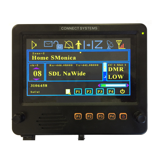
- Page 51 Zone Favorites When you select Zone Favorites, you get the following screen. You can get here directly by pressing the name of the zone on the touch screen from the home page. To select a favorite zone, use the right rotary knob or the up and down keys to select the zone you want to jump to and then press the solid circle or the P4 key.
- Page 52 Note that just above the caption "Home SMonica" it says Zone = 5. That tells you the zone number that channel is on. Below that caption, you will see ch = 5. That is the channel number. The 05 refers to the channel number within the zone.
- Page 53 After you finished entering the zone number, press the “O” key from the keypad of the DTMF microphone, the P4 key, or the black circle on the display above the P4 key. The new favorite zone will be stored, and the display will jump to the home screen with the zone you just picked.
- Page 54 Channel Favorites When you select Channel Favorites, you get the following screen. You can get here directly by pressing the name of the channel on the touch screen from the home page. To select a favorite channel, use the right rotary knob or the up and down keys to select the zone you want to jump to and then press the solid circle or the P4 key.
- Page 55 If you want to add a new favorite channel, first move the box to a free channel or to an existing channel. Then press the “1” key on the keypad of the DTMF microphone. The box will then be erased and the box will show “zone = chan =“...
- Page 56 Note that just below the caption "Home SMonica" it says ch = 5. That tells you the channel number that channel is on. The 08 refers to the channel number within the zone. The Zone number is above the caption " Home SMonica ".
- Page 57 Spectrum View The spectrum view is a built in spectrum analyzer. It shows frequency verses amplitude. There are two parameters than can be adjusted in this screen…. Step size and center frequency. To access these parameters, press the select key. You can select between the step sizes by the right encoder or the up and down keys on the display, P2 and P3, and the keypad on the DTMF microphone.
- Page 58 Step size This is the step size when adjusting the Rx frequency. The possible entries are: 10 Hz 20 Hz 50 Hz 100 Hz 250 Hz 500 Hz 1,000 Hz 5,000 Hz 10,000 Hz 25,000 Hz 50,000 Hz 100,000 Hz 250,000 Hz 500,000 Hz 1,000,000 Hz...
- Page 59 FRONT OF THE CS-BFD The P1, P2, P3, and P4 corresponds to the P1, P2, P3, P4 on the CS800D. When used with other radios, they might have different meanings. The two knobs on the edges correspond to the rotary knob on the CS800D and the Up and Down button on the CS800D.
- Page 60 The interface to the radios have the following connections: Pin 1 (SPGND) This is the speaker ground connection from the radio. It goes directly to the internal speaker of the CS-BFD. Pin 2 (SPOUT) This is the speaker audio connection from the radio.
- Page 61 Pin 7 (MIC) This is the direct audio connection from the microphone Pin 8 (GND) This is the common ground for the power and audio Interface to the DTMF Microphone Pin 1 (MBL) Not used Pin 2 (8V) Power required by the microphone. Pin 3 (GND) Ground Pin 4 (PTT) Push to talk from the microphone Pin 5 (ME) Microphone Ground...
Need help?
Do you have a question about the CS-BFD and is the answer not in the manual?
Questions and answers