Table of Contents

Related Manuals for AIS AutoChlor CHROME-20

Summary of Contents for AIS AutoChlor CHROME-20
- Page 1 Special Edition RESIDENTIAL SALT WATER CHLORINE GENERATOR INSTRUCTION MANUAL This manual is for: CHROME STARTER MODELS CHROME-20 CHROME-30 CHROME PREMIUM MODELS CHROME-20.P CHROME-30.P Includes: TIME CLOCK MODELS (battery backup optional)
-
Page 2: Trademark Acknowledgements
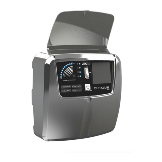
DISCLAIMER • While every effort has been made to ensure that the information contained in this guide is accurate and complete, no liability can be accepted for any errors or omissions. • Australian Innovative Systems Pty Ltd reserves the right to change the specifications of the hardware and software described herein at any time without prior notice. - Page 3 Fig. 1 1. High Salt Light 5. Chlorine Controller If the light is on or flashing see Turn clockwise to increase the chlorine Warning Indicator Lights, page 9. output and anti-clockwise to reduce the chlorine output. 2. Low Salt / Cell Off Light If the light on or flashing see (Note: When production lights are off, Warning Indicator Lights, page 9.
-
Page 4: Special Note
THE CHROME SALT WATER CHLORINATION SYSTEM Congratulations on your choice of CHROME salt water chlorinator system for your swimming pool. The CHROME salt water chlorinator you have purchased is designed for easy and simplistic operation and maintenance. By following these instructions you are assured years of trouble free operation. -
Page 5: Water Balance
Using only refined swimming pool salt add the desired quantity to the swimming pool water. To assist in the rapid dissolving and mixing, sweep or brush the solids until they are fully dissolved. Undissolved salt may result in staining your pool finish. As salt is heavier than water it will continue to lie at the deepest point of your pool, even though the salt granules themselves have fully dissolved. - Page 6 SPECIAL NOTE ON CHLORINE: Your salt water chlorinator is not designed to bring your pool from a zero chlorine reading to an acceptable level but rather to maintain acceptable levels. Should it become necessary due to unforeseen circumstances (such as the unlikely event of chlorinator malfunction, severe weather patterns, or massive use of the swimming pool) that you find your pool requires additional chlorine then chlorine should be manually added rather than running your filter and chlorinator excessively to replace the lost chlorine.
-
Page 7: Installing The Power Supply
GAS TRAP INSTALLATION Fig. 2 GAS SENSOR GAS TRAP EXAMPLE GAS TRAP IN IMPLEMENTATION IMPLEMENTATION • Each Electrode housing contains a sensor that detects gas presence. If water was to stop flowing and the chlorine generator continue running, chlorine gas pressure will build up CARTRIGE in the housing and pipe work and cause damages. -
Page 8: Circuit Breaker
1. Pump 2. Filter 3. Water heater 4. Power supply for chlorine generator 5. Chlorine generator electrode Fig. 3 POWER SUPPLY CONTROL FUNCTIONS Your CHROME salt water chlorination system has been designed for simplistic operation and control. The functions and controls (both standard and optional) and their various operations will give you a greater understanding and knowledge of the control and maintenance of both your CHROME unit and your pool (refer to Fig. -
Page 9: Warning/Indicator Lights
PUMP OUTPUT SOCKET A 240 volt pump output power socket is supplied and located on the right hand underside of the power supply. Your pool pump power supply lead should be plugged into this socket so that when the time clock switches at your designated times both the salt water chlorinator and pool pump will activate in unison. -
Page 10: Normal Operation
...continued WARNING INDICATOR LIGHTS (FIG. 1, ITEMS 1,2,3 & 4) 3. RED LIGHT: STEADY POWER ON FLASHING NO WATER FLOW chlorinator on standby STEADY – During normal operation this light will remain STEADY, indicating that power is on and the chlorinator is operating correctly. FLASHING –... - Page 11 At the end of each cell operational cycle (or cell reverse), the power on/no water flow light & overload light (Fig. 1, Items 3 & 4) will ALTERNATE by flashing in a slow fashion for approximately thirty (30) seconds. This is the cell rinse procedure and is part of the normal operation, which occurs at each reverse cycle change of your CHROME™...
- Page 12 TIME CLOCK OPERATIONS (TIMER MODELS ONLY) ...continued (FIG. 1, ITEM 7) Start and stop times are set by pushing in the small grey time setting elements at the extreme outside of the time clock face and exposing a red mark. Each element represents fifteen minutes and these should be positioned showing the red marks at the times you wish your filter plant and chlorinator to operate.
-
Page 13: Clock Setting
INSTRUCTIONS FOR MACHINES WITH BATTERY BACKUP TIMER DESCRIPTION OF MODE SWITCH MODE SWITCH POSITION CONTENT CURRENT TIME DISPLAY SETTING TIMER PROGRAM ON-OFF TIME CURRENT TIME CLOCK ADJUSTMENT CLOCK SETTING If the timer displays 23:30 Thursday, it must be changed to 8.15 Sunday. Detailed operation is as follows: Set the Mode switch to “Clock”... -
Page 14: Program Setting
PROGRAM SETTING To set the program of “7:30 ON, ~16:30 OFF”, “Operation of Monday to Friday”. 1. Set the Mode switch to Program. Setting screen for “TURN-ON Time” will appear. 2. Select “TURN-ON TIME” with Hour, Min and Day and set with Enter button. -
Page 15: Manual Switch Operation
RESET When pressed Reset button, all the contents to be set are cancelled. After indicated all the displays lighted for 4 seconds, “00 00” will flash. If pressed other button than reset, clock starts from “0:00”. MANUAL SWITCH OPERATION POSTION, OPERATION LCD DISPLAY OUTPUT FUNCTION DESCRIPTION... - Page 16 TIMER BY-PASS SWITCH (TIMER MODELS ONLY) (FIG. 1, ITEM 8) If your CHROME chlorinator has a timer by-pass switch fitted you will find this located on the front panel on the right hand side of the time clock. This switch allows you to bypass timer functions without the need to use the auto –...
-
Page 17: Important Note
Set your chlorine controller to achieve maximum and optimum results for your pool situation. Please remember that an over chlorinated pool is not a healthy pool, so it may not be necessary for you to run your chlorinator at maximum output to maintain recommended chlorine levels. Your CHROME salt water chlorinator is fitted with a sophisticated electronic circuit board which is designed to minimise the need for manual operations and maximise cell life by constantly managing the correct operation of the power supply and electrolytic cells. - Page 18 CLEANING THE ELECTROLYTIC CELLS From time to time it will become necessary to clean calcium and other deposits that will form on the chlorinator electrolytic cell plates. Cleaning maintenance of the cells will vary from one pool to the next depending on water conditions and calcium build up rate on the electrodes. Cleaning times will also vary from model to model.
- Page 19 position. You are now ready to resume filter and chlorination operations. REMEMBER a clean electrolytic cell will extend the cell life as well as producing maximum chlorine without the necessity of running the power supply at continually higher settings. By keeping your cell in a clean state at all times you are effectively safe guarding your investment and maximizing the cell life of your salt water chlorinator SPECIAL NOTE ON CLEANING CELLS...
-
Page 20: Installation
Using the same, award-winning technology that has made AutoChlor one of Australia’s most well-known and trusted brands, in an AIS first pool owners now have the luxury of choosing the AutoChlor CHROME... -
Page 21: Technical Specifications
Stylish design and reliability at an entry level price. Perfect for first home buyers, investors or anyone wishing to enjoy all the benefits of in-line salt water chlorination. Comes with standard CHROME AIS Genuine Anodes and a 12 month warranty. Can be easily upgraded to a Premium unit in the future. -
Page 22: Warranty And Service
WARRANTY AND SERVICE The manufacturer offers a one (1) year warranty on the power supply and electrolytic cell on CHROME Starter Model chlorinators and a (3) year warranty on the power supply and electrolytic cell on CHROME Premium Model chlorinators. This warranty applies to the original purchaser and is not transferable. - Page 24 AIS Contacts Head Offi ce +61 7 3396 5222 or 1300 965 222 (Australia wide) Email: info@aiswater.com.au Facsimile +61 7 3393 3441 WARRANTY HOTLINE 1800 676 076 (Australia wide) Australian Innovative Systems 51 Millennium Place, Tingalpa, Queensland 4173 Australia www.aiswater.com.au...
Need help?
Do you have a question about the AutoChlor CHROME-20 and is the answer not in the manual?
Questions and answers