ADTRAN 239 H4R Installation And Maintenance Manual
Hdsl4 repeater
Hide thumbs
Also See for 239 H4R:
- Brochure (2 pages) ,
- Installation and maintenance practice (28 pages)
Table of Contents
Advertisement
Quick Links
CONTENTS
1. GENERAL .............................................................. 1
2. INSTALLATION ................................................... 2
3. FRONT PANEL FEATURES ................................ 5
4. HDSL4 DEPLOYMENT GUIDELINES ............... 6
5. MAINTENANCE ................................................. 10
6. SPECIFICATIONS ............................................... 10
7. WARRANTY AND CUSTOMER SERVICE ...... 10
FIGURES
Figure 1. ADTRAN 239 H4R .....................................1
Figure 2. HDSL4 Circuit Segments ............................. 6
Repeaters .....................................................8
Repeaters (Example) .................................. 9
TABLES
Table 1. Card Edge Pin Assignment ......................... 2
Table 2. Compliance Codes ...................................... 3
Housings ..................................................... 3
Housings ..................................................... 4
Table 5. LED Indicators ........................................... 5
Ω
) .................................................... 7
Table 7. ADTRAN 239 H4R Specifications .......... 11
1. GENERAL
This practice provides installation and maintenance
(I/M) instructions for the ADTRAN 239 T1 HDSL4
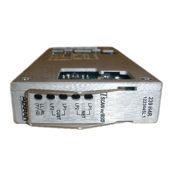
Repeater (H4R), P/N 1221445L1. Figure 1 is an
illustration of the H4R. H4R equipment features
include:
• TC PAM line coding
• Lightning protection
• In-band loopback control
• Standard 239 form factor repeater apparatus case
design
• Remote provisioning and pass-through
performance monitoring
61221445L1-5A
239 H4R
HDSL4 Repeater
Installation and Maintenance
Section 61221445L1-5, Issue 1
Trademarks: Any brand names and product names included in this document are
trademarks, registered trademarks, or trade names of their respective holders.
239 H4R
1221445L1
Figure 1. ADTRAN 239 H4R
An ADTRAN span powered HDSL4 circuit consists
of an H4TU-C, up to two H4Rs and an H4TU-R. Due
to span power limits, the number of H4Rs permitted in
the circuit depends on the type of H4TU-C used. An
ADTRAN 239 H4R provides DS1 transport on all
revised resistance design (RRD) 26 AWG and/or 24
AWG loops. Two ADTRAN 239 H4R repeaters
extend the range of a loop up to 42.5 kft (24 AWG).
Repeater placement on single H4R loops depends only
on the attenuation properties of the loop segment.
Repeater placement for dual H4R loops requires both
segment attenuation and segment DC resistance
requirements be satisfied (refer to section 4, HDSL4
Deployment Guidelines).
Section 61221445L1-5A
Issue 1, June 2002
CLEI Code: T1R5YP3D_ _
LP1
NET
LP2
LP1
CUST
LP2
LL RL
/
(Y) (G)
1
Advertisement
Table of Contents

Related Manuals for ADTRAN 239 H4R


Summary of Contents for ADTRAN 239 H4R
-
Page 1: Table Of Contents
Table 1. Card Edge Pin Assignment ......2 LL RL (Y) (G) Table 2. Compliance Codes ........3 Table 3. 239 H4R Capacity Guidelines for ADTRAN Housings ............. 3 Table 4. 239 H4R Capacity Guidelines for Other Housings ............. 4 Figure 1. -
Page 2: Installation
The ADTRAN 239 H4R is designed for deployment 1221403L6…..DDM+ H4TU-C using any 239-type repeater case. A retainer patch is 1221404L1…..3192 H4TU-C available for use with the 239 H4R for securing into the 1221404L4…..3192 H4TU-C ADTRAN apparatus cases. 1221404L6…..3192 H4TU-C 1221407L4…..Soneplex® H4TU-C When installing the ADTRAN 239 H4R, refer to the 1221426L1…..T200 H4TU-R... -
Page 3: Table 2. Compliance Codes
– H4R Capacity Guidelines The ADTRAN 239 H4R is designed for installation in a prewired apparatus case, and the capacity guidelines for deployment are defined in Table 3 and Table 4. These housing capacity numbers are based upon testing results. -
Page 4: Table 4. 239 H4R Capacity Guidelines For Other Housings
61221445L1-5A Section 61221445L1-5, Issue 1... -
Page 5: Front Panel Features
3. FRONT PANEL FEATURES The ADTRAN H4R front panel has five LEDs indicating different states of the HDSL4 circuit. Table 5 explains the meaning of the different LED indicators. Table 5. LED Indicators Five Tricolored Front Panel LEDs Indicate these H4R States. -
Page 6: Hdsl4 Deployment Guidelines
1221404L6) support only one H4R in the including Insertion Loss and Pulse Attenuation. HDSL4 circuit. The different segments of an HDSL4 circuit are The ADTRAN HDSL4 system provides DS1-based defined in Figure 2. services over loops designed to comply with the guidelines given below. -
Page 7: Table 6. Single Pair Cable Dc Resistance Value ( )
Each of the three segments associated with span powering two H4Rs and an H4TU-R must satisfy the recommended insertion loss, loop attenuation requirements in addition to the DC resistance budgets. In general, 22 and 19 AWG segments will be restricted by their loop attenuation while the DC resistance will restrict the segment reach for 26 and 24 AWG. -
Page 8: Figure 3. Resistance Budget Span Powering Two Repeaters
4. Find the instance where the two points from steps Once the resistance of each segment is confirmed, refer to Figure 3 to decide if the H4TU-C is capable 2 and 3 meet on the graph. of span powering two H4Rs and one H4TU-R. 5. -
Page 9: Figure 4. Resistance Budget Span Powering Two Repeaters (Example)
An example problem is illustrated in Figure 4. For 4. Find the instance on the graph where the points this example, begin with three known measurements: from steps 2 and 3 meet. 700 ohms first segment resistance, 800 ohms second 5. -
Page 10: Maintenance
(CO). If a malfunction is confirmed, replace the unit. service. Refer to ADTRAN U.S. and Canada Carrier Networks Equipment Warranty, Document The ADTRAN 239 H4R has looping capability through 60000087-10. the channel allowing digital loopback in fault isolation. The looping is accomplished remotely. -
Page 11: Figure 1. Adtran 239 H4R
Table 7. ADTRAN 239 H4R Specifications i t a l a i i l e s r i t s r , t n , t n . e l l l a i t a i t c i l e i t c <... - Page 12 61221445L1-5A Section 61221445L1-5, Issue 1...
Need help?
Do you have a question about the 239 H4R and is the answer not in the manual?
Questions and answers