
Summary of Contents for ZOLL Road Safety RS-4000
- Page 1 Road Safety RS-4000 System Overview and Installation Version 4.13 ZO 5.2.0.85 Updated 6/28/16...
- Page 2 © 2016 ZOLL Data Systems, Inc. All rights reserved. CONFIDENTIAL TRADE SECRETS – DO NOT DISCLOSE.
- Page 3 ZOLL Online’s Road Safety application is the back end interface tool for managing and configuring the RS-4000 devices. In the final section of this document (Appendix F), you will find all of the details necessary for using ZOLL Online to properly prepare the vehicles and devices for a successful installation.
- Page 4 ZOLL ONLINE ELEARNING COURSE A large section of this document is dedicated to the ZOLL Online configuration of the RS-4000 units. Although this section does include all of the necessary information needed to setup the devices and make them operable, addition details and training on the full scope of the Road Safety product is available at no additional charge.
-
Page 5: Table Of Contents
RS-4000 & Digital Ally Integration ....................5 Hardware Identification and Inventory Sheet ................. 6 Optional items that can be purchased from ZOLL by the agency ........8 Component Locations and Connectivity Overview ................ 9 RS-4902 – Spotter Switches: ....................9 RS-4000 - On-Board Computer .................... - Page 6 Diagnostic Viewer Menu Options ..................34 Testing ............................ 35 Calibration ..........................37 ZOLL Online Setup of the RS-4000 On-Board Computer ..........37 Test drive and final check with ZOLL Online ................. 38 Required Documentation ......................39 Form 1: Vehicle Inspection Diagram ..................40 Form 2: Vehicle Inspection Form ...................
- Page 7 Engine RPM Scale Values ..................... 56 Vehicle Speed Scale Values ..................56 Calibrating Speed and RPM Scale Values ................56 Appendix E: ZOLL Online’s Road Safety Application ..............60 1. Supported browsers ......................60 2. Log into ZOLL Online ......................60 3.
-
Page 8: Purpose
BUILD SHEET ZOLL does not have access to all year/make/model vehicles and some research by the installers will likely be required. Input/output and connection information including vehicle wire colors and common connection points can be obtained (when available) by calling ZOLL Road Safety Support at 1-800-663-3911 option 9. -
Page 9: Parts Inventory
PARTS INVENTORY Use the ZOLL-Hardware Identification + Inventory Sheet (pages 6 - 8) to inventory the ZOLL provided hardware. To order additional or replacement parts, such as Driver ID tags, Call ZOLL support for additional information: 1-800- 663-3911 option 9. -
Page 10: Rs-4000 Overview
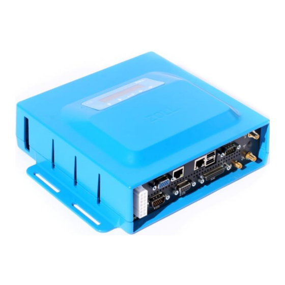
RS-4000 OVERVIEW The ZOLL 4000 is an on-board driver modification and data acquisition system that monitors and reports vehicle speed, vehicle RPM, 16 additional user definable digital single ended inputs and 6 differential inputs. There are 2 digital outputs. The digital... -
Page 11: Vcan
Input Voltage for Logic 1: 8-18VDC: Absolute Maximum: 40 VDC. Maximum Differential Input Voltage for Logic 0: 0.75 VDC. Minimum Differential Input Voltage for Logic 1: 5.0 VDC. © 2016 ZOLL Data Systems, Inc. All rights reserved. CONFIDENTIAL TRADE SECRETS – DO NOT DISCLOSE. -
Page 12: Digital Outputs
Road Safety, please see Appendix E for additional information on its setup and configuration. NOTE: A detailed set of installation/integration instructions can be found in APPENDIX E of this document. © 2016 ZOLL Data Systems, Inc. All rights reserved. CONFIDENTIAL TRADE SECRETS – DO NOT DISCLOSE. -
Page 13: Hardware Identification And Inventory Sheet
HARDWARE IDENTIFICATION AND INVENTORY SHEET IMPORTANT: Upon delivery of the RS-400 equipment, the shipment should be inspected for completeness and condition. Any shortage or damage should be documented and immediately reported to the ZOLL support team at 1-800-663-3911 or support@zoll.com... - Page 14 RS-0202 WiFi Antenna RS-4203 GPS Antenna RS-4902 Unsafe Reverse Spotter Switch Kit RS-4301 Speaker Additional optional items listed on the following page. © 2016 ZOLL Data Systems, Inc. All rights reserved. CONFIDENTIAL TRADE SECRETS – DO NOT DISCLOSE.
-
Page 15: Optional Items That Can Be Purchased From Zoll By The Agency
OPTIONAL ITEMS THAT CAN BE PURCHASED FROM ZOLL BY THE AGENCY RS-2213 Driver ID RS-3212-25 Driver ID Tags Programmer Kit (Package of 25) RS-4105 Standard I/O Harness RS-3144 Sprinter Harness RS-DVM250B Digital Ally 250 - 2 Camera Event Data RS-4106 Mercedes... -
Page 16: Component Locations And Connectivity Overview
Typical wire harness routing is through the center overhead or outboard exterior light voids. Connects to: RS-4000 On-Board Computer via the Standard Digital Harness. See Appendix C for wiring assignments. © 2016 ZOLL Data Systems, Inc. All rights reserved. CONFIDENTIAL TRADE SECRETS – DO NOT DISCLOSE. -
Page 17: Rs-4000 - On-Board Computer
OEM imposed length limit for the OBDII/CAN cable of 16 feet (4.87 meters). *Extensions to the cable are not recommended or supported by ZOLL. DO NOT modify the cable RS-4202 – WINDOW MOUNT GPS ANTENNA Determine the installation location of the antenna on the windshield or dashboard. Keep in mind that the GPS antenna cannot "see"... -
Page 18: Rs-3211-1 - Driver Id Receptacle
Mounting the speaker in other locations further from the driver creates the need for higher volume settings. Connects to: RS-4000 On-Board Computer via the Power/Audio harness. © 2016 ZOLL Data Systems, Inc. All rights reserved. CONFIDENTIAL TRADE SECRETS – DO NOT DISCLOSE. -
Page 19: Connectivity Overview
CONNECTIVITY OVERVIEW See Appendix C for wiring assignments. © 2016 ZOLL Data Systems, Inc. All rights reserved. CONFIDENTIAL TRADE SECRETS – DO NOT DISCLOSE. -
Page 20: Zoll Online Prerequisites
If the vehicle being installed has not been completely setup in ZOLL Online the install SHOULD NOT proceed past STEP 17: CONNECTING DIGITAL OUTPUTS. Each agency must have a tenant account configured in ZOLL Online. Customers using multiple ZOLL Online applications will use the tenant already in use for their other products. -
Page 21: Hardware Installation
Complete a thorough interior and exterior inspection of the vehicle with the customer using the Vehicle Inspection Diagram (Form 1) and the ZOLL Road Safety Vehicle Inspection Form (Form 2). Before starting the installation, identify and document any damage or inoperable systems, and notify the responsible party. You can find forms 1 and 2 in the back of this document. -
Page 22: Step 2: Identify Component Installation Locations
Extensions to the cable are not recommended or supported by ZOLL. DO NOT modify this cable. 1. If you are going to mount the On-Board Computer under a seat, ZOLL recommends that you remove it for easier access, and verify adequate clearance. -
Page 23: Step 4: Prepare Harnesses For Looming And Appropriate Routing
Typical Routing -Separate the speaker wires which will route aft to above and behind the driver’s seat. See Page 42 and Form 3 Build Sheet for wiring assignments. © 2016 ZOLL Data Systems, Inc. All rights reserved. CONFIDENTIAL TRADE SECRETS – DO NOT DISCLOSE. - Page 24 This “Polarity” should be noted for use in configuring ZOLL Online. © 2016 ZOLL Data Systems, Inc. All rights reserved.
- Page 25 1. Locate and identify the vehicles OBDII port (driver’s side dash) and unbolt the connector. 2. Mount the connector end of the ZOLL OBDII Harness in its place and connect the vehicle’s port to the matching receptacle on the ZOLL OBDII cable. Secure all wiring to prevent interference with vehicle foot controls or any other moving components under the dash.
-
Page 26: Step 5: Mount The Rs-4301 Audio Speaker
(Speaker volume is not adjustable by the driver and must be done through ZOLL Online) 1. Check for clearance behind the panel for the screws that will secure the speaker. -
Page 27: Step 6: Mount The Rs-3211-1 Driver Id Receptacle
2. Pass the wires through a 15/16” or 24mm deep socket, position socket onto the nut and hand tighten only. 3. Connect the wires from the receiver to RS-4105 Expansion harness wires. © 2016 ZOLL Data Systems, Inc. All rights reserved. CONFIDENTIAL TRADE SECRETS – DO NOT DISCLOSE. -
Page 28: Step 7: Mount The Spotter Switches (Rs-4902 Kit)
Effort should be made to have the switches placed in the same relative position throughout the entire fleet of similar vehicle types to assist the crew in locating them. © 2016 ZOLL Data Systems, Inc. All rights reserved. CONFIDENTIAL TRADE SECRETS – DO NOT DISCLOSE. - Page 29 Spotter Switch Connectivity © 2016 ZOLL Data Systems, Inc. All rights reserved. CONFIDENTIAL TRADE SECRETS – DO NOT DISCLOSE.
-
Page 30: Step 8: Connecting The Seatbelt Input
8. See Appendix C and Form 3 Build Sheet for wiring assignments. © 2016 ZOLL Data Systems, Inc. All rights reserved. CONFIDENTIAL TRADE SECRETS – DO NOT DISCLOSE. -
Page 31: Step 9: Mount The Rs-4202 Window Mount Gps Antenna
50% of the bond strength is achieved after 20 minutes. Avoid contact with the antenna for a minimum of 20 minutes after initial installation. © 2016 ZOLL Data Systems, Inc. All rights reserved. CONFIDENTIAL TRADE SECRETS – DO NOT DISCLOSE. -
Page 32: Step 10: Connecting Turn Signal Inputs
Once located, test and verify the connection points provide the required voltage, note the polarity, and annotate your build sheet with the location and color of the wires used for use later in ZOLL Online. Route the White/Brown and White/Yellow wires safely using wire loom if needed to their connection points and solder splice the connections. -
Page 33: Step 15: Connecting The Power And Ground Inputs
Once located, test and verify the connection points, note the polarity, and annotate your build sheet with the location and color of the wires used for use later in ZOLL Online. Route the Brown/Yellow and Grey/Yellow wires safely using wire loom if needed to their connection points and solder splice the connections. Tape the splice and secure the wiring. -
Page 34: Step 18: Connecting A Cellular Modem Or Wi-Fi
Wi-Fi connectivity limits the real time functionality of the system and data will only be available for viewing in ZOLL Online upon completion of a download while the vehicle is connected to the access point. - Page 35 RS-4000 out of hibernation. A Windows desktop should be present or will appear after the RS-4000 boots up. © 2016 ZOLL Data Systems, Inc. All rights reserved. CONFIDENTIAL TRADE SECRETS – DO NOT DISCLOSE.
- Page 36 3. Click the START button in the lower right corner of the screen. 4. Click on CONTROL PANEL © 2016 ZOLL Data Systems, Inc. All rights reserved. CONFIDENTIAL TRADE SECRETS – DO NOT DISCLOSE.
- Page 37 5. Click on NETWORK AND SHARING CENTER 6. Click on CONNECT TO A NETWORK © 2016 ZOLL Data Systems, Inc. All rights reserved. CONFIDENTIAL TRADE SECRETS – DO NOT DISCLOSE.
- Page 38 8. Enter the network security key for the selected network, and then click OK. 9. From the NETWORK AND SHARING CENTER screen, click on your connection in the VIEW YOUR ACTIVE NETWORK portion of the screen. © 2016 ZOLL Data Systems, Inc. All rights reserved. CONFIDENTIAL TRADE SECRETS – DO NOT DISCLOSE.
- Page 39 10. Click on the WIRELESS PROPERTIES button. © 2016 ZOLL Data Systems, Inc. All rights reserved. CONFIDENTIAL TRADE SECRETS – DO NOT DISCLOSE.
- Page 40 15. Once successful, close all open windows on the R-S4000 desktop, disconnect the monitor, keyboard, and mouse. Connectivity setup is complete. © 2016 ZOLL Data Systems, Inc. All rights reserved. CONFIDENTIAL TRADE SECRETS – DO NOT DISCLOSE.
-
Page 41: Step 19: Completing The Installation
Options in below can be used with little or no harm to the system. Options in should only be used when directed by ZOLL Support. NOTE: The RS-4000 must maintain internet connectivity to receive the settings and configuration data from ZOLL Online during testing. -
Page 42: Testing
SxS Port Status UIB Port Status Tenant Key Vehicle Key m. Serial Number *must match serial number on the sticker* contact ZOLL if mismatched. n. WAN Connectivity o. WAN Connectivity p. ZOLL RescueNet Road Safety Running There are four possible statuses: blue, green, yellow and red. - Page 43 *Screen shot the above and the event tab after cycling through all inputs. And include with the documentation sent to ZOLL. Label the vehicle name on the screen shot. © 2016 ZOLL Data Systems, Inc. All rights reserved.
-
Page 44: Calibration
ZOLL. For customers self-installing the RS-4000 follow the steps below. 1. Log in to ZOLL Online and configure steps 6-18. This will allow you to set up a vehicle name, vehicle class, audible tones, orientation index number, and calibration settings. -
Page 45: Test Drive And Final Check With Zoll Online
(Login, Reverse (spotter switch), Seatbelt, Over force, and Over speed if safe to do so.) If the vehicle was configured to communicate via the vehicle’s cellular modem, data will be visible in ZOLL Online REPORTS after uploading is complete. -
Page 46: Required Documentation
REQUIRED DOCUMENTATION As part of a ZOLL Certified installation, forms 1-4 are required to be completed and submitted to ZOLL Support for inclusion in the account records. Form 1, Vehicle Damage Inspection Form - Document any areas where damage or an unusual condition exists, and should be reflected on form 2, the vehicle inspection form. -
Page 47: Form 1: Vehicle Inspection Diagram
FORM 1: VEHICLE INSPECTION DIAGRAM © 2016 ZOLL Data Systems, Inc. All rights reserved. CONFIDENTIAL TRADE SECRETS – DO NOT DISCLOSE. -
Page 48: Form 2: Vehicle Inspection Form
FORM 2: VEHICLE INSPECTION FORM © 2016 ZOLL Data Systems, Inc. All rights reserved. CONFIDENTIAL TRADE SECRETS – DO NOT DISCLOSE. -
Page 49: Form 3: Build Sheet
FORM 3: BUILD SHEET © 2016 ZOLL Data Systems, Inc. All rights reserved. CONFIDENTIAL TRADE SECRETS – DO NOT DISCLOSE. -
Page 50: Form 4: Post Installation Verification Worksheet
FORM 4: POST INSTALLATION VERIFICATION W ORKSHEET © 2016 ZOLL Data Systems, Inc. All rights reserved. CONFIDENTIAL TRADE SECRETS – DO NOT DISCLOSE. -
Page 51: Form 5: Serial Number Assignment Form
FORM 5: SERIAL NUMBER ASSIGNMENT FORM © 2016 ZOLL Data Systems, Inc. All rights reserved. CONFIDENTIAL TRADE SECRETS – DO NOT DISCLOSE. -
Page 52: Appendix A: Printable Component Locations Diagram
NOTE: Location should be within 16 feet of the driver’s side dashboard. There is an OEM limit of 16 feet for the OBDII/CAN Harness. © 2016 ZOLL Data Systems, Inc. All rights reserved. CONFIDENTIAL TRADE SECRETS – DO NOT DISCLOSE. - Page 53 Mounting the speaker in other locations further from the driver greatly reduces effectiveness as its volume is limited. Connects to: On-Board Computer via Power/Audio Harness. © 2016 ZOLL Data Systems, Inc. All rights reserved. CONFIDENTIAL TRADE SECRETS – DO NOT DISCLOSE.
-
Page 54: Appendix B: Orientation Index
The RS-4000 On-Board Computer can be mounted in any of 24 unique positions. When configuring the unit in ZOLL Online, refer to the chart below and images following to determine the appropriate Orientation Index Number to use for your installation. When mounting the unit, ensure it is level, (perpendicular or vertical) and either parallel or square to the centerline of the vehicle. -
Page 55: Orientation Index 1-4
ORIENTATION INDEX 1-4 The On-Board Computer’s mounting tabs are on the bottom, and parallel to the floor, ZOLL logo and screen facing up. The ambulance is shown as a reference to how the RS-4000 would be mounted inside the vehicle. -
Page 56: Orientation Index 5-8
ORIENTATION INDEX 5-8 The On-Board Computer’s mounting tabs are on top, and parallel to the floor, ZOLL logo and screen facing down (mounted under a shelf). Orientation 5 - ZOLL logo DOWN, connectors facing Orientation 6 - ZOLL logo DOWN, connectors facing FRONT. -
Page 57: Orientation Index 9-12
ORIENTATION INDEX 9-12 The On-Board Computer is mounted vertically, perpendicular to the floor, ZOLL logo and screen facing forward (wall mounted). Orientation 9 - ZOLL logo FRONT, connectors facing Orientation 10 - ZOLL logo FRONT, connectors facing DOWN. Orientation 11 - ZOLL logo FRONT, connectors facing Orientation 12 - ZOLL logo FRONT, connectors facing LEFT. -
Page 58: Orientation Index 13-16
ORIENTATION INDEX 1 3-16 The On-Board Computer is mounted vertically, perpendicular to the floor, ZOLL logo and screen facing rearward (wall mounted). Orientation 13 - ZOLL logo facing REAR., connectors Orientation 14 - ZOLL logo facing REAR., connectors facing UP. -
Page 59: Orientation Index 17-20
ORIENTATION INDEX 1 7-20 The On-Board Computer is mounted vertically, perpendicular to the floor, ZOLL logo and screen facing left (right wall mounted). Orientation 17 - ZOLL logo facing LEFT, connectors Orientation 18 - ZOLL logo facing LEFT, connectors facing UP. -
Page 60: Orientation Index 21-24
ORIENTATION INDEX 2 1-24 The On-Board Computer is mounted vertically, perpendicular to the floor, ZOLL logo and screen facing right (left wall mounted). Orientation 21 - ZOLL logo facing RIGHT, connectors Orientation 22 - ZOLL logo facing RIGHT, connectors facing UP. - Page 61 This page left intentional blank © 2016 ZOLL Data Systems, Inc. All rights reserved. CONFIDENTIAL TRADE SECRETS – DO NOT DISCLOSE.
-
Page 62: Appendix C: Wiring Assignments
Speaker "+" to RS Audio Speaker Speaker "-" Ribbed Black Speaker "-" to RS Audio Speaker Digital Output Yellow To Device Controller Digital Output Orange To Device Controller © 2016 ZOLL Data Systems, Inc. All rights reserved. CONFIDENTIAL TRADE SECRETS – DO NOT DISCLOSE. -
Page 63: Appendix D: High Speed Digital Input Installation & Setup
Auto Discovery and to set the host value to 127.0.0.1 before pressing the Start button. The following screenshot shows the main screen of the Diagnostic Viewer Utility after it has been connected to the target RS4000 unit. © 2016 ZOLL Data Systems, Inc. All rights reserved. CONFIDENTIAL TRADE SECRETS – DO NOT DISCLOSE. - Page 64 2. Setting Configuration Options You can set Configuration options for High Speed RPM Connection Type by using ZOLL Online. In ZOLL Online, go to: Administration>Road Safety>Road Safety Configurations>Devices> and then click on the vehicle you’re working with and make sure that the RPM Connection Type is set to High Speed and complete the Add/Edit Device screen.
- Page 65 After the RS4000 has been configured for high speed inputs on ZOLL Online, the RS4000 may generate violation tones until speed and RPM have been calibrated. 3. Calibrating RPM In the Diagnostics Viewer application, 0pen the High Speed Calibration window by clicking the wheel icon.
- Page 66 Once the calibration results have been tested and found to be acceptable, the settings must be saved. Save the settings by clicking the fourth icon from the left on the Diagnostic Viewer toolbar. See the figure below for an example screenshot. © 2016 ZOLL Data Systems, Inc. All rights reserved. CONFIDENTIAL TRADE SECRETS – DO NOT DISCLOSE.
-
Page 67: Appendix E: Zoll Online's Road Safety Application
APPENDIX E: ZOLL ONLINE’S ROAD SAFETY APPLICATION As mentioned at the very beginning of this document, ZOLL Online plays a very important role in the Road Safety System. ZOLL Online houses the Road Safety application, which is used to not only configure and manage the onboard RS-4000 devices, but the entire Road Safety system. -
Page 68: Main Screen-Home Page
As seen in the screen shot above, the initial page to which you’re taken once logged into ZOLL Online is the “My Products” page. You can see the”Administration” link has been circled. It should also be noted that the “Administration”... -
Page 69: Product Administration Screen
After clicking on “Administration” or “Admin” you’re taken to the screen where you can select the product you wish to administer. The selections here will vary based upon which ZOLL products the agency uses. Obviously, you’ll want to select “Road Safety”. -
Page 70: Vehicle Screen
Click “SAVE” when done and you will be returned to the list of vehicles. Next, starting with “Vehicle Group Settings” we’ll configure our Road Safety settings. Press the “Admin” button from the top of the screen. © 2016 ZOLL Data Systems, Inc. All rights reserved. CONFIDENTIAL TRADE SECRETS – DO NOT DISCLOSE. -
Page 71: Road Safety Configurations Screen - Vehicle Group Settings
To configure the group settings for the vehicle, click on “Vehicle Group Settings”. As with most of the ZOLL Online configuration sections, when you first enter the section you can either modify existing entries by clicking on their name or add new items by clicking on the plus (+) icon. Once you’re in the area where you’re adding or modifying entries, you’ll see that the top section allows you to add the name of your... - Page 72 Based upon our experience with the system and consultations with our clients, typical values are being provided where applicable. These are not recommendations or suggestions. These settings need to be tailored to the agency’s policies and procedures. © 2016 ZOLL Data Systems, Inc. All rights reserved. CONFIDENTIAL TRADE SECRETS – DO NOT DISCLOSE.
- Page 73 RPM values will obviously vary greatly based upon different factors and discussed with the agency. © 2016 ZOLL Data Systems, Inc. All rights reserved. CONFIDENTIAL TRADE SECRETS – DO NOT DISCLOSE.
- Page 74 This section allows for the entry of up to four different GPS Destinations. If configured here in Road Safety the GPS information acquired from the RS-4000 will be sent to the destinations from ZOLL Online. If this setup is requested by the agency they will be required to provide the installer values for the four fields shown in the image.
-
Page 75: Road Safety Configurations Screen - Inputs
Click the vehicle group your vehicle is assigned to (or add a new set of inputs). Put a check in the Create Report box. The inputs must be assigned as follows: © 2016 ZOLL Data Systems, Inc. All rights reserved. CONFIDENTIAL TRADE SECRETS – DO NOT DISCLOSE. - Page 76 © 2016 ZOLL Data Systems, Inc. All rights reserved. CONFIDENTIAL TRADE SECRETS – DO NOT DISCLOSE.
- Page 77 Siren Click “SAVE” when finished to return to the Input screen, then click to return to the Road Safety Configuration screen. Configure Devices next. © 2016 ZOLL Data Systems, Inc. All rights reserved. CONFIDENTIAL TRADE SECRETS – DO NOT DISCLOSE.
-
Page 78: Road Safety Configurations Screen - Devices
5. Click SAVE at the bottom of the page when complete. Once all Devices have been properly configured, click to return to the Customize Road Safety screen. Configure Inputs next. © 2016 ZOLL Data Systems, Inc. All rights reserved. CONFIDENTIAL TRADE SECRETS – DO NOT DISCLOSE. -
Page 79: 10. Vehicle Installation Verification
10. VEHICLE INSTALLATION VERIFICATION Once all of the ZOLL Online Road Safety configurations have been set and the RS-4000 devices has been completely installed and calibrated, it should be ready to go live with the customer. Using the “Reports” section of ZOLL Online’s Road Safety can provide one final system test to ensure the functionality of the vehicle(s). - Page 80 Data type & Selection type – These fields are inactive for this type of report. b. Once the values have been entered, press the “Save and view” button. © 2016 ZOLL Data Systems, Inc. All rights reserved. CONFIDENTIAL TRADE SECRETS – DO NOT DISCLOSE.
- Page 81 5. If after polling the data, the ZOLL Online Road Safety system displays a report similar to the image below, you can feel very confident that the vehicle’s RS-4000 is communicating successful with the Road Safety system. Here’s a quick rundown on some of the information being displayed and how to interact with the report: “Events”, “Speed”, “longitudinal G-Force”, “Lateral G-Force”...
- Page 82 This testing procedure should be performed for all vehicles to ensure their installation has been successfully completed. © 2016 ZOLL Data Systems, Inc. All rights reserved. CONFIDENTIAL TRADE SECRETS – DO NOT DISCLOSE.
-
Page 83: Appendix F: Digital Ally / Rs-4000 Trigger Connection And Setup
Digital Ally Inc. is a manufacture of in-vehicle audio/video recording devices. Recordings are triggered by both the Digital Ally devices themselves and the ZOLL RS-4000. The RS-4000 can be tightly integrated with both the DVM- 250 (two camera system) and the DVM-250+ (three camera system). - Page 84 Using a wire/sensor other than Orange #2 will require a slight modification to the sensor setup process described below.. © 2016 ZOLL Data Systems, Inc. All rights reserved. CONFIDENTIAL TRADE SECRETS – DO NOT DISCLOSE.
-
Page 85: Dvm-250/250+ Configuration Manager / Camera Setup
Prior to being able test or utilize the DVM-250/250+ system, the devices must be configured using Digital Ally’s “Configuration Manager” software. Just as some setup work in ZOLL Online needs to be completed before the RS- 4000 will function, the same holds true for the Digital Ally system. DVM-250/250+ configurations must be setup using the Configuration Manager software for the device to properly function. -
Page 86: The General Tab
Days in LPS – This field allow for the setting of the number of days the camera will stay in Please change this setting to a value standby mode before it’s completely powering down. of at least 1. © 2016 ZOLL Data Systems, Inc. All rights reserved. CONFIDENTIAL TRADE SECRETS – DO NOT DISCLOSE. -
Page 87: The Recording Tab
4. 4 – Cameras – The default values displayed are the suggested initial settings for the devices. © 2016 ZOLL Data Systems, Inc. All rights reserved. CONFIDENTIAL TRADE SECRETS – DO NOT DISCLOSE. -
Page 88: Motion Tab
2. Vehicle Speed – This value should be set based upon the highest vehicle speed acceptable under the agencies safety policy. © 2016 ZOLL Data Systems, Inc. All rights reserved. CONFIDENTIAL TRADE SECRETS – DO NOT DISCLOSE. -
Page 89: Sensors
2. Configured the drop-down fields as follows: 3. Click the “Done” button (where the edit button was) and this will save the configurations for this sensor. © 2016 ZOLL Data Systems, Inc. All rights reserved. CONFIDENTIAL TRADE SECRETS – DO NOT DISCLOSE. -
Page 90: Distributing The Configurations
DO NOT remove the deviceconfig file from the SD card. The camera should now be setup to receive triggers from the RS-4000 device. © 2016 ZOLL Data Systems, Inc. All rights reserved. CONFIDENTIAL TRADE SECRETS – DO NOT DISCLOSE. -
Page 91: Accessing Recorded Video Files
For assistance setting up a wireless connection between your DVM-250/250+ camera and a secure storage computer or any other camera related support issues or questions, please contact Digital Ally at Phone: 800-440-4947 Email: support@digitalallyinc.com © 2016 ZOLL Data Systems, Inc. All rights reserved. CONFIDENTIAL TRADE SECRETS – DO NOT DISCLOSE. -
Page 92: Preparing The Rs-4000 Output 2
The RS-4000 energizes the orange output wire with 12 vdc for .5 to 1 second when a configured threshold has been exceeded. The ZOLL Road Safety Diagnostics viewer is used to configure the RS-4000 device to send this output for each of the violations detected by the device. - Page 93 Diagnostics viewer. To save, simply press the fourth button from the left on the button bar. Not saving prior to exiting will require the re-entry of all values. © 2016 ZOLL Data Systems, Inc. All rights reserved. CONFIDENTIAL TRADE SECRETS – DO NOT DISCLOSE.
-
Page 94: Testing The Rs-4000, Digital Ally Dvm-250/250+ Integration
The Spotter Switch violation time is a configurable value in ZOLL Online. 20 seconds is a suggested amount of time but it may be different based upon the agency. -
Page 95: Rs-4000 / Digital Ally Trouble Shooting Summary
This following excerpt is taken directly from the troubleshooting section of the Digital Ally installation guide. For additional assistance contact: ZOLL Support – 1-800-663-3911 / support@zoll.com Digital Ally – 1-800-440-4947 / support@digitalallyinc.com © 2016 ZOLL Data Systems, Inc. All rights reserved. CONFIDENTIAL TRADE SECRETS – DO NOT DISCLOSE. -
Page 96: Appendix G: Installation Quick Reference Sheet
APPENDIX G: INSTALLATION QUICK REFERENCE SHEET © 2016 ZOLL Data Systems, Inc. All rights reserved. CONFIDENTIAL TRADE SECRETS – DO NOT DISCLOSE.
Need help?
Do you have a question about the Road Safety RS-4000 and is the answer not in the manual?
Questions and answers