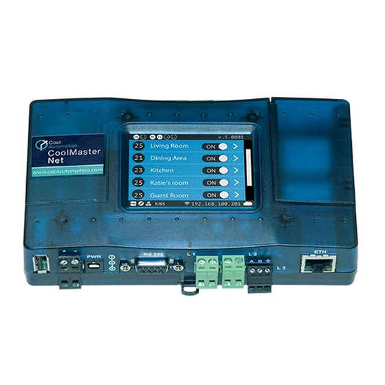
Cool Automation CoolMasterNet Quick Installation Manual
Universal hvac bridge
Hide thumbs
Also See for CoolMasterNet:
- Quick installation manual (43 pages) ,
- Quick installation manual (38 pages) ,
- Quick installation manual (24 pages)
Summary of Contents for Cool Automation CoolMasterNet
- Page 1 CoolMasterNet Universal HVAC Bridge Quick Installation Guide Experts in HVAC Integration and Controls...
- Page 2 Need more help? Visit us http://coolautomation.com/support Email us support@coolautomation.com...
- Page 3 Any lack of electric circuit or any deficiency caused by installation may result in an electric shock or fire. Do not relocate or reinstall the CoolMasterNet by yourself. Any deficiency caused by your own re-installation may result in an electric shock or fire.
- Page 4 CAUTION Do not allow children to play with the CoolMasterNet and supervise them not to get access to the appliance. CoolMasterNet is not to be used by persons with reduced physical, sensory or mental capabilities, or lack of experience and knowledge.
- Page 5 High temperature area or directly flamed point. Heating and/or fire can occur. f) Moist area, where there is exposure to water. If water enters the inside of the CoolMasterNet, it may cause electric shock and electrical components may fail.
-
Page 6: What's In The Box
What’s In the Box CoolMasterNet AC Power supply adapter 100V-240V 50/60hz to 12V Optional 1 RS232 DB9 Male to Female 1 USB-Mini USB 1 Ethernet cable cable cable... - Page 7 Universal HVAC bridge for the integration of Home Automation / BMS and HVAC. CoolMasterNet USB Host RS485 L4 — HVAC Line 4 Power Ethernet Port USB Device Port Power Plug GPIOs DIP Switches P, Q, R, S ...
- Page 8 Preconfigured CoolMasterNet Type label Configuration stickers for HVAC line L1 Sticker for identifying the configuration of This label uniquely identifies the manufacturer’s the CoolMasterNet on L1. configuration of CoolMasterNet. Located on the back of the enclosure. Daikin 9-24 , 350...
- Page 9 How to connect CoolMasterNet to HVAC HVAC connectivity — on L1 HVAC Communication Terminals Connect to the communication terminals on the HVAC equipment: HVAC communication terminal’s names* Daikin Mitsubishi Electric Panasonic (Sanyo) Toshiba Hitachi * For Heat Recovery systems the connection is at outdoor equipment only.
- Page 10 How to connect CoolMasterNet to HVAC HVAC connectivity — on L7 HVAC Communication Terminals Connect to the communication HVAC Terminal terminals on the HVAC: HVAC communication terminal’s names InterA InterB Mitsubishi Heavy Gree* Samsung * For LG, Gree and Samsung systems the connection is at outdoor equipment only.
- Page 11 SetPoint temperature indication. 23 102 Indoor unit operation button (on/off) 25 103 Service settings button CoolMasterNet MAC address 25 104 CoolMasterNet internal network IP CoolRemote connectivity status MACADDR00001 192.168.0.1 Connected Disconnected Connection error with error code...
- Page 12 How to connect CoolMasterNet to Home Automation and BMS systems Home Automation, BMS & CoolRemote Router Internet RS232 RS485 Ethernet Home Automation / BMS CoolRemote App...
-
Page 13: Power Supply
How to connect CoolMasterNet to Power supply Power Supply Option A Option B AC Power supply adapter (Included in the Box) Direct DC power supply 12V-24V DC 12V DC 100V-240V AC Direct DC power supply from 50/60hz local electrical panel... - Page 14 Enter the details manually on the Type Label sticker OUTPUT: OUTPUT: 9-24 , 350 To auto fill-in all the CoolMasterNet details for INPUT: v DC located on the type label is the SN and the PIN code for CoolRemote App.
-
Page 15: Mounting On Din Rail
CoolMasterNet Universal HVAC Bridge ® AABBCCDDEE How to mount on a DIN rail L1 L2 CoolRemote Mounting on DIN rail OUTPUT: 9-24 , 350 INPUT: v DC 00000000000 L6 L7 Slide under the mount feet CoolMasterNet Secure the rail in place Universal HVAC Brid ®... -
Page 16: Mounting On Wall
CoolMasterNet ® Universal HVAC Bridge AABBCCDDEE L1 L2 CoolRemote 156mm OUTPUT: For mounting the CoolMasterNet with wall screws, please see attached template with 1:1 dimensions. 90mm 1:1 scale mounting template for wall screws 21 mm 38.5 mm 79 mm Distance between two mounting holes... - Page 17 Changing the dip switches, while DC voltage is present on L1, may damage the CoolMasterNet. For Daikin/Mitsubishi Electric non-VRV/VRF equipment, DC voltage supply by CoolMasterNet might be required for proper operation. Make sure CoolMasterNet is disconnected from power. Measure DC voltage on HVAC communication line L1 ...
- Page 18 Appendix: Dip Switches setup for VRV/VRF HVAC system on L1 HVAC systems setup on L1 Daikin Mitsubishi Electric Toshiba Panasonic (Sanyo) Hitachi...
- Page 19 Appendix: Dip Switches setup for VRV/VRF HVAC system on L7 HVAC systems setup on L7 Mitsubishi Heavy Samsung Gree...
- Page 20 Appendix: GPIOs application All On, all Off operation by external signal All On All Off...


Need help?
Do you have a question about the CoolMasterNet and is the answer not in the manual?
Questions and answers