Advertisement
Table of Contents
Thank you for purchasing the G320X drive. The G320X DC servo drive is warranted to be free of manufacturing defects for 1 year
from the date of purchase. Any customer who is dissatisfied with it or is unable to make it work will be cheerfully refunded the
purchase price if the G320X is returned within 15 days of the purchase date.
PLEASE READ FIRST BEFORE USING THE G320X:
If you are not familiar with DC servo drives please do the following setup instructions with the motor on the bench before mounting it
on the mechanism it will eventually run. This will allow you to get a baseline motor behavior of what to expect.
Before you start, you must have a suitable encoder mounted and properly aligned on the motor. Follow the manufacturer's
instructions on mounting and aligning the encoder if the motor doesn't already come with one.
Next you must have a DC power supply suitable for the motor. The power supply current rating must equal the maximum current
you expect to run the motor at.
Finally, have a STEP and DIRECTION pulse source available.
Before going on, turn the "P", "I", "D", and LIMIT trimpots to the 11 o'clock position. The trimpots are single-turn so be careful not to
over-torque them.
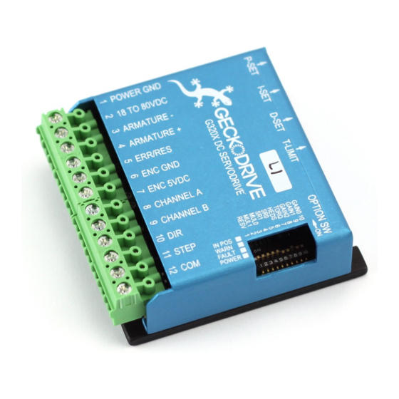
G320X PINOUT
TERMINAL 1
Power Ground
Connect the negative (black) lead of your power supply to this terminal.
TERMINAL 2
Power (+)
Connect the positive (red) lead of your power supply to this terminal. It must be between +18VDC to +80VDC.
TERMINAL 3
Armature (-)
Connect the black lead of your motor to this terminal.
TERMINAL 4
Armature (+)
Connect the red lead of your motor to this terminal.
TERMINAL 5
ERR/RES
This is the ERROR and RESET pin. For a full explanation read the section titled "ERROR/RESET PIN" on page
6.
TERMINAL 6
Encoder Ground
Connect the encoder power supply ground to this terminal.
TERMINAL 7
Encoder +5VDC
Connect the encoder +5VDC pin to this terminal.
TERMINAL 8
Channel A
Connect the Channel A pin of your encoder to this terminal.
TERMINAL 9
Channel B
Connect the Channel B pin of your encoder to this terminal.
TERMINAL 10
Direction
Connect the DIRECTION signal to this terminal.
TERMINAL 11
Step
Connect the STEP signal to this terminal.
TERMINAL 12
S/D Common
Connect this terminal to either +5VDC or signal ground.
G320X SERVO DRIVE
REV 10: May 13, 2010
1
Advertisement
Table of Contents

Subscribe to Our Youtube Channel
Related Manuals for Geckodrive G320X

Summary of Contents for Geckodrive G320X
- Page 1 REV 10: May 13, 2010 Thank you for purchasing the G320X drive. The G320X DC servo drive is warranted to be free of manufacturing defects for 1 year from the date of purchase. Any customer who is dissatisfied with it or is unable to make it work will be cheerfully refunded the purchase price if the G320X is returned within 15 days of the purchase date.
- Page 2 REV 10: May 13, 2010 DIP SWITCH SETTINGS The G320X has a 10 position DIP switch that is accessible when the cover is removed. These switch settings control many of the features of the G320X and are labeled SW1 through SW10.
- Page 3 Connect the power supply (+) to this terminal STEP 3: TESTING THE ENCODER At this point the encoder should be tested for functionality. You can test the encoder on the G320X by watching the indicator LEDs on the board. Turn on the power supply. The FAULT indicator (red LED) should be on for 1 second and then turn off. The IN-POSITION indicator (green LED) should turn on and remain on.
- Page 4 The default PID trimpot settings should work in most applications. The PID settings do not in any way affect the positioning accuracy of the G320X and only affects the settling time of the servo. If you use an oscilloscope (probe on TP1) an optimally tuned servo will...
-
Page 5: Current Limit
The trimpot setting is proportional to current; if it is set to full scale it will be outputting 20A, half scale will output 10A, quarter scale will output 5A, and so on. The behavior of the trimpot is controlled by DIP SW 10. If SW 10 is on (default), the G320X will limit the current to the trimpot setting until it runs into an excessive load. - Page 6 ERROR output. Otherwise, the following details are important. The ERROR output is latched in the “ERROR” state (Terminal 5 = “0”) by the power-on reset circuitry in the G320X. It will stay in this state indefinitely until it is cleared by applying +5V to this terminal for at least 1 second.
-
Page 7: Option Switches
G320X SERVO DRIVE REV 10: May 13, 2010 G320X Servodrive Option Switches Status LEDs G320X SPECIFICATIONS Power Supply: +18VDC to +80VDC Quiescent Current: 30mA Motor Current: 0 to 20 Amps Motor Inductance: At least 1mH Short Circuit Protect: 22A trip...
Need help?
Do you have a question about the G320X and is the answer not in the manual?
Questions and answers