Table of Contents
Advertisement
Quick Links
Advertisement
Table of Contents

Related Manuals for Diversified Technology CPB-4612

Summary of Contents for Diversified Technology CPB-4612
- Page 1 Artisan Technology Group is your source for quality new and certified-used/pre-owned equipment SERVICE CENTER REPAIRS WE BUY USED EQUIPMENT • FAST SHIPPING AND DELIVERY Experienced engineers and technicians on staff Sell your excess, underutilized, and idle used equipment at our full-service, in-house repair center We also offer credit for buy-backs and trade-ins •...
- Page 2 CPB4612 CPCI Board with a Intel® Pentium® M © Copyright 2005 by Diversified Technology, Inc. All rights reserved. Printed in the United States of America. No part of this publication may be reproduced, stored in a retrieval system, or transmitted, in any form or by any means, electronic, mechanical, photocopying, recording, or otherwise without prior permission of the publisher.
- Page 3 The product should be returned in its original shipping materials. Contact DTI if replacement material is required. Seal the carton securely and ship prepaid to the following address with the RMA number on the label. DIVERSIFIED TECHNOLOGY, INC. Service Department 476 Highland Colony Parkway P.O.
-
Page 4: For Your Safety
CPB4612 Configuration and Maintenance Guide For Your Safety CAUTION: The cPB-4612 contains a lithium battery. This battery is not field-replaceable. There is a danger of explosion if the battery is incorrectly replaced or handled. Do not disassemble or recharge the battery. Do not dispose of the battery in fire. When the battery is replaced, the same type or an equivalent type recommended by the manufacturer must be used. -
Page 5: Revision History
CPB4612 Configuration and Maintenance Guide Revision History Date Revision Summary of Corrections 08/31/04 Initial Release 10/12/04 Added links throughout manual. 8/19/05 Removed references to ethernet signal routing. Update BIOS Section... -
Page 6: Table Of Contents
CPB4612 Configuration and Maintenance Guide Table of Contents Return Shipment Information ...........................ii For Your Safety ..............................iii Revision History ..............................iv Table of Contents..............................v Tables ..................................ix Figures ..................................ix Document Organization............................x INTRODUCTION......................1 Product Definition ..............................2 Features.................................4 Functional Blocks ..............................4 1.3.1 CompactPCI/PSB Architecture..........................5 1.3.2 Processor................................6 1.3.3... - Page 7 CPB4612 Configuration and Maintenance Guide Operating System Installation...........................17 CONFIGURATION ....................19 Switch Descriptions ............................21 3.1.1 PB1 (Reset) ................................21 3.1.2 J16-1 (BKT-GND to GND) ..........................21 3.1.3 J16-2 (+12V to J5-pin D1)..........................22 3.1.4 J16-3 (+5V PMC I/O) ............................22 3.1.5 J16-4 (IMPI Disable) ............................22 3.1.6 J17-1 (Not Used)..............................22 3.1.7...
- Page 8 CPB4612 Configuration and Maintenance Guide 7.3.2 Preload Value 2 (BAR+04h)..........................35 7.3.3 General Interrupt Status (BAR+08h) .........................36 7.3.4 Reload Register (BAR+0Ch) ..........................36 Using the Watchdog in an Application ......................37 7.4.1 WDT Unlocking and Programming Sequence....................37 7.4.2 Watchdog Reset ..............................37 7.4.2.1 Load Preload Values ............................37 7.4.2.2 Enabling the Watchdog Reset ..........................37 7.4.2.3 Reloading the Watchdog............................37 SYSTEM BIOS......................
- Page 9 CPB4612 Configuration and Maintenance Guide J15 (CompactPCI Bus Connector)........................71 J11 (CompactPCI Bus Connector)........................72 J8 (CompactPCI Connector) ..........................73 J2 (Rear Panel I/O CompactPCI Connector) ....................74 J1 (10/100 Ethernet) ............................75 J4 (Universal Serial Bus 0 connector).......................75 J3 (COM1 Serial Port) ............................76 J6, J7, J9, J10 (64bit/66Mhz PCI Mezzanine Connectors) ................76 B.10 J12 and J13 (32bit/33Mhz PCI Mezzanine Connectors).................80 B.11...
- Page 10 Functional Block Diagram ........................... 5 Memory Address Map Example ........................14 I/O Address Map ............................... 15 Setup Screen ..............................17 Default Jumper Configuration ........................... 21 PCB Dimensions ............................... 66 CPB-4612 Connectors Locations (Topside) ..................... 69 Backplane Connectors - Pin Locations ......................70...
-
Page 11: Document Organization
This chapter can be used to compare the features of the CPB-4612 against the needs of a specific application. Chapter 2, "Getting Started," provides unpacking instructions and initial setup information for the CPB-4612. -
Page 12: Introduction
The CPB-4612 is a 64-bit compliant CompactPCI Pentium M single board computer designed to operate in either a system slot or a peripheral slot. The cPB-4612 provides Ethernet integration using the Intel 82559 10/100 Base-T PCI Ethernet controller and the Intel 82546EB Fast Gigabit Ethernet Multifunction PCI Controller. -
Page 13: Product Definition
4612 includes an Intelligent Platform Management Bus (IPMB) for system management along with IPMI v1.5 compatible firmware. The cPB-4612 occupies a single 6U high Eurocard slot. The board can be used in either a system master slot or in a peripheral slot. Though the cPB-4612 is highly integrated, its capabilities can be extended with pluggable PMC modules. -
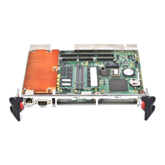
Page 14: Cpb-4612 Faceplate
CPB-4612 Faceplate Ejector Handle 10/100 Ethernet COM RS-232 Serial Port Reset Switch Hotswap LED Ejector Handle... -
Page 15: Features
1.2 Features There are two SKU's of the cPB-4612. The first is the cPB-4612, which has a 64bit/66Mhz PMC site and a 32bit/33Mhz PMC site. . The second is the cPB-4612 w/ IDE, which has a 64bit/66Mhz PMC site and an on-board 2.5”... -
Page 16: Compactpci/Psb Architecture
Functional Block Diagram 1.3.1 CompactPCI/PSB Architecture The cPB-4612 is designed to operate in a PICMG 2.0 CompactPCI backplane. If the system is placed in a system slot, the bridge will automatically configure itself as a transparent bridge, and the board will perform as the host. -
Page 17: Processor
The cPB-4612 has a 64bit/66Mhz PCI-X bridge to the CompactPCI backplane. The bridge will configure itself as a transparent bridge when the board is in a system slot, so that the cPB-4612 can be the system host. If the cPB-4612 is placed in a peripheral slot, the bridge configures itself as a non-transparent bridge, and will show up as a PCI device to the host. -
Page 18: Memory And I/O Addressing
(5V supply), 3.0V (3.3V supply), and 10.0V (+12V supply). 1.3.7 Rear-Panel I/O The following I/O signals are available from the J5 connector at the back of the cPB-4612. These signals are available for use by a rear panel transition board such as the cRT-4612. -
Page 19: 10/100 Ethernet Interface
1.3.12 IDE Hard Drive The cPB-4612 w/IDE supports an onboard ATA/100 2.5” IDE interface. This can be used to connect a 2.5” hard drive. The IDE interface is implemented using Intel’s 6300ESB I/O Controller Hub (ICH). Note that the onboard 2.5”... -
Page 20: Counter/Timers
Appendix D provides a link to the datasheet for this device. 1.3.18 Reset The push-button reset on the cPB-4612's faceplate functions as a "Hard Reset". See Chapter 4, "Reset," for more information about reset sources for the cPB-4612. 1.3.19 Two-Stage Watchdog Timer The watchdog timer optionally monitors system operation and is programmable for different timeout periods (from 1 microsecond to 10 minutes). -
Page 21: Universal Serial Bus (Usb)
USB, simplifying cabling requirements. The cPB-4612 provides one USB port at its faceplate (connector J20 is Port 0). USB Port 1 and USB port 2 are routed to the cPB-4612’s J5 Rear Panel I/O connector. -
Page 22: Getting Started
Chapter 2 Getting Started This chapter summarizes the information needed to make the cPB-4612 operational. This chapter should be read before using the board. -
Page 23: Unpacking
BIOS Identification string displayed during the Power On Self Test (POST). 2.2.2 Connectivity The cPB-4612 features an ejector handle that is keyed for compatible slots. The board can only be inserted into slots fitted with a compatible mating key. -
Page 24: Memory Configuration
Local PCI bus. Any memory not reserved or occupied by a local memory device (DRAM/flash) is available to PCI memory devices. The cPB-4612 can support up to two sticks of either 256 MB, 512 MB, 1 GB DDR SDRAM. 1MB of ®... -
Page 25: Memory Address Map Example
Memory Address Map Example 4 GB FFF80000h - FFFFFFFFh SYSTEM BIOS/Flash 4 GB - 512 KB 8000000h - FFF7FFFFh PCI PERIPHERALS 512 MB 100000h - 1FFFFFFFh SYSTEM MEMORY 1 MB E0000h - FFFFFh SYSTEM BIOS 896 KB C8000h - DFFFFh BIOS EXTENSION C0000h - C7FFFh 800 KB... -
Page 26: I/O Configuration
2.4 I/O Configuration The cPB-4612 addresses up to 64 KB of I/O using a 16-bit I/O address. The cPB-4612 is populated with many commonly used I/O peripheral devices. The I/O address location for each peripheral is shown in the "I/O Address Map" illustration. -
Page 27: Connectors
"Connectors" topic in Appendix B for complete connector descriptions and pin outs. 2.6 Jumper Options The cPB-4612 provides several jumper configuration options for features that cannot be provided through the BIOS Setup Utility. Location figures and descriptions are provided in Chapter 3, "Configuration."... -
Page 28: Operating System Installation
SECURITY/VIRUS F1 General Help Esc Exit EXIT Copyright (c) 2004, Diversified Technology, Incorporated 2.8 Operating System Installation For more detailed information about your operating system, refer to the documentation provided by the operating system vendor. 1. Install peripheral devices. CompactPCI* devices are automatically configured by the BIOS during the boot sequence. - Page 29 5. Proceed with the OS installation as directed, being sure to select appropriate device types if prompted. Refer to the appropriate hardware manuals for specific device types and compatibility modes of DTI products. 6. When installation is complete, reboot the system and set the boot device order in the SETUP boot menu appropriately.
-
Page 30: Configuration
Chapter 3 Configuration The cPB-4612 has been designed for maximum flexibility. Many features can be configured by the user for specific applications. Most configuration options are selected through the BIOS Setup utility (discussed in the "BIOS Configuration Overview" topic in Chapter 2). Some options cannot be software... -
Page 31: Jumper Cross-Reference Table
Jumper Options and Locations The cPB-4612 contains a push-button switch on the faceplate and eight jumpers on the component side of the board. The jumpers are listed and briefly described in the "Jumper Cross-Reference" table below. Factory default switch settings are shown in the "Default Jumper Settings" figure. -
Page 32: Switch Descriptions
The following topics list the switches in numerical order and provide a detailed description of each switch. 3.1.1 PB1 (Reset) PB1 is a push-button on the front of the cPB-4612. Pressing PB1 issues a hard reset. Reset is discussed in more detail in Chapter 4. -
Page 33: J16-2 (+12V To J5-Pin D1)
WARNING: Not placing the voltage key, placing the voltage key at the wrong location, or using a PMC card that is not tolerant of the set voltage may damage the PMC card and/or the cPB-4612 board. J16-3 CMOS Real Time Clock... -
Page 34: J17-3 (Disable Onboard Video)
3.1.10 J18 (Ejector Switch) The ejector handles are used when cPB-4612 is inserted or removed (hot swapped) from a chassis that is powered on. When a customer wishes to remove a board from a system that is powered on then the ejector handles should be opened just enough to disengage the handles from the chassis, but without fully disengaging the J-connectors from the back of the chassis. -
Page 35: Reset
Chapter 4 Reset This chapter discusses the reset types and reset sources on the cPB-4612. If necessary, the cPB-4612’s board reset characteristics can be tailored to the requirements of a specific system. -
Page 36: Reset Types And Sources
4.1 Reset Types and Sources The cPB-4612’s reset types are listed below. The sources for each reset type are detailed in the following topics. • Hard Reset: All devices are held in reset. • Soft Reset: CPU initialization only. Other devices are not reset. -
Page 37: Nmi Sources
4.1.4 NMI Sources Watchdog Timer (System Register Address 79h) The watchdog timer may be programmed to generate a non-maskable interrupt if it is not strobed within a given time-out period. This function is discussed in Chapter 7, "Watchdog Timer."... -
Page 38: System Monitoring And Control
Chapter 5 System Monitoring and Control The cPB4612 has an IPMI System Monitor that complies with PICMG® 2.9 specification, and complies with IPMI Specification 1.5. This allows a PICMG 2.9 compliant chassis that utilizes a chassis manager, or Baseboard Management Controller (BMC) to detect the presence of the cPB4612 and make Field Replaceable Unit (FRU) information, and Sensor Device Records (SDR’s) available. -
Page 39: Monitoring And Control Functions
5.1 Monitoring and Control Functions The IPMI System Monitor has a dedicated serial interface to the host processor on the cPB4612. It is a 16550-compatible UART that is configurable in SETUP. If this interface is not required, it can be disabled. -
Page 40: Field Replaceable Unit (Fru) Information
Firmware updates are possible through either the serial or IPMB interface. A special utility will be provided should a firmware update be necessary. 5.6 SMBus Address Map The table below lists the location, function, and address of each SMBus device used on the cPB-4612. Device cPB-4612 Function... -
Page 41: Ide Controller
IDE devices. The IDE controller is incorporated into the Intel 6300ESB, which supports ATA- 100. There is one 50-pin IDE connector on the cPB-4612 with IDE, which supports up to two IDE devices (though there is only space on the board itself to mount one device). The secondary IDE channel is available through the rear panel connector (J5). -
Page 42: Features Of The Ide Controller
The cPB-4612 supports internal and external IDE devices. These configurations are described below. 6.2.1 Primary IDE Channel The cPB-4612’s primary IDE channel is directed to the J14 IDE connector. J14 is used to interface with the locally mounted hard drive. -
Page 43: Watchdog Timer
Chapter 7 Watchdog Timer This chapter explains the operation of the cPB-4612’s watchdog timer. It provides an overview of watchdog operation and features, as well as sample code to help you learn how the watchdog timer works with applications. -
Page 44: Watchdog Timer Overview
The watchdog timer is implemented by using the 6300ESB ICH integrated watchdog timer. The primary function of the watchdog timer is to monitor the cPB-4612’s operation and take corrective action if the software fails to function as programmed. The major features of the watchdog timer are: •... -
Page 45: Wdt Configuration Register (60H)
7.2.2 WDT Configuration Register (60h) Offset: 60-61h Default Value: Size: 16 bits Attribute: Description 15-6 Reserved WDT_OUTPUT: Output Enable This bit indicates whether or not the WDT will toggle the WDT_TOUT# pin if the WDT times out. Reserved WDT_PRE_SEL: Prescaler Select The WDT provides two options for prescaling the main down counter. -
Page 46: Memory Mapped Registers
Description Reserved WDT_TOUT_CNF: Timeout configuration 0 – Watchdog Timer Mode 1 – Free Running Mode WDT_ENABLE: Watchdog Enable 0 – Disabled 1 - Enabled WDT_LOCK Setting this bit will lock values of this register until a hard reset occurs or power is cycled. 0 –... -
Page 47: General Interrupt Status (Bar+08H)
Description 31:20 Reserved 19:0 Preload_Value_2 7.3.3 General Interrupt Status (BAR+08h) Offset: BAR+08h Default Value: Size: 8 bits Attribute: R/WC Description Reserved Watchdog Timer Interrupt Active This bit is set when the first stage of the 35 bit down counter reaches zero. This is a sticky bit and is cleared by writing a ‘1’. -
Page 48: Using The Watchdog In An Application
7.4 Using the Watchdog in an Application The following topics are provided to aid you in learning to use watchdog in an application. 7.4.1 WDT Unlocking and Programming Sequence Unlocking and programming the WDT Memory Mapped registers involves the following sequence: 1. -
Page 49: System Bios
Chapter 8 System BIOS The embedded BIOS on the cPB-4612 is implemented as firmware that resides in the on-board flash read-only memory (ROM). The BIOS contains standard PC-compatible basic input/output (I/O) services and several DTI specific functions and features. Support for applicable SBC peripheral devices (SCSI, NIC, video adapters, etc.), that are also loaded into the SBC flash ROM, will not be specified in this document. -
Page 50: Bios Upgrade And Recovery
BIOS Upgrade and Recovery To reprogram the BIOS or update it if it becomes corrupted, use the DTIFLASH.EXE utility available from DTI and discussed later in this chapter. 8.1.1 Flash Utility Program DTIFLASH.EXE is a utility program that can be obtained from DTI in the event a BIOS should be updated. Run DTIFLASH.EXE to modify the BIOS in the on-board flash memory. -
Page 51: Boot Menu
Once the memory is present, the compressed portions of the BIOS are de-compressed into the shadow memory occupying the standard BIOS memory ranges. The BIOS can now scan for and initialize other interfaces such as I/O devices and items on the PCI or ISA busses. If a video adapter is in the system it is located and initialized. -
Page 52: Rom Utilities
devices within a category (such as to boot from IDE hard drive instead of SCSI), or to permanently change the boot order, you will have to enter SETUP and change the boot options. If any errors are detected up to this point they will now be displayed on the screen along with the following prompt to direct further actions. - Page 53 ROM Utilities SYSTEM SUMMARY Displays various information about the system installed SYSTEM SETUP Used to configure the time/date, floppy drive types, and other BIOS options HARD DISK SETUP Used to configure the hard drive types BOOT ORDER Used to specify boot device ordering PERIPHERALS Used to enable/disable onboard I/O devices USB CONFIG...
-
Page 54: System Summary
↑↓ Select Screen Enter Go to Sub Screen SECURITY/VIRUS F1 General Help Esc Exit EXIT Copyright (c) 2004, Diversified Technology, Incorporated System Summary Descriptions CPU Type: Displays the processor brand string from the processor installed. CPU: Displays the current speed of processor installed. -
Page 55: System Setup
USB CONFIG Bootup Num-Lock MISC. CONFIG SYSTEM OPTIONS CPU Speed 1.7 GHz EVENT LOGGING MPS Revision SECURITY/VIRUS ↑↓ Select Screen Enter Go to Sub Screen F1 General Help Esc Exit EXIT Copyright (c) 2004, Diversified Technology, Incorporated System Setup Descriptions... - Page 56 System Time: A new time is set by typing in the HOUR, MINUTE, and SECONDS each followed by pressing < ENTER >. The time is displayed in 24-hour format; therefore, AM hours range from 0 through 11 and the PM hours range from 12 through 23.
-
Page 57: Ide Config
SLAVE ↑↓ Select Screen Enter Go to Sub Screen F1 General Help Esc Exit Copyright (c) 2004, Diversified Technology, Incorporated IDE Config Descriptions Onboard PCI IDE Controller: This item selects the configuration for the onboard parallel and serial IDE controllers. -
Page 58: Hard Disk Setup
Block (Multi-Sector Transfer) Mode Auto PIO MODE Auto DMA MODE Auto S.M.A.R.T. Auto 32Bit Data Transfer Disabled ARMD Emulation Type Auto ↑↓ Select Screen Enter Go to Sub Screen F1 General Help Esc Exit Copyright (c) 2004, Diversified Technology, Incorporated... - Page 59 Hard Drive Setup Descriptions The configuration options described below work identically for HARD DRIVES 0 - 3. Device: Displays the type of IDE device currently installed. Type choices include Not Installed, Hard Disk, ATAPI CDROM, and ARMD. Vendor: Displays the manufacturer device identification information. Size: Displays the storage capacity of the device.
-
Page 60: Boot Order
PERIPHERALS HARD DISK DRIVES USB CONFIG 1st Drive PM-IBM-DJSA-220 MISC. CONFIG REMOVABLE DEVICES 1st Drive USB Disk EVENT LOGGING ↑↓ Select Screen Enter Go to Sub Screen SECURITY/VIRUS F1 General Help Esc Exit EXIT Copyright (c) 2004, Diversified Technology, Incorporated... - Page 61 Boot Order Descriptions Boot Device Priority: Selects the boot order for installed bootable devices. The BIOS attempts to boot in descending order beginning from the top of the list. ATAPI CDROM Drives: Boot from an IDE CDROM. Hard Disk Devices: Boot from hard disk drive.
-
Page 62: Peripherals
Serial Port Mode 115200 8,n,1 Flow Control None Terminal Type ANSI VT-UTF8 Combo Key Support Disabled Redirection After BIOS POST Always ↑↓ Select Screen Enter Go to Sub Screen F1 General Help Esc Exit Copyright (c) 2004, Diversified Technology, Incorporated... - Page 63 Onboard Peripheral Control Descriptions Video Controller: This item displays the enable/disable status of the onboard video controller. Graphics Memory Select: Selects the amount of system memory used by the internal graphics device. The choices are 1MB, 4MB, 8MB, 16MB, or 32MB. Ethernet Controller: This item controls the enable/disable of the 10/100 Ethernet controller.
-
Page 64: Usb Configuration
USB MASS STORAGE CONFIG USB Mass Storage Reset Delay 20 Sec MISC. CONFIG Device #1 USB DISK Emulation Type Auto EVENT LOGGING ↑↓ Select Screen Enter Go to Sub Screen SECURITY/VIRUS F1 General Help Exit EXIT Copyright (c) 2004, Diversified Technology, Incorporated... - Page 65 USB Control Descriptions USB Function: Enables USB host controllers. May be enabled for all ports, specific ports, or no ports. USB 2.0 Controller: Controls the USB 2.0 Controller. When enabled, the system will support high-speed (480 Mbps) USB devices, provided the OS loads a driver for the 2.0 Controller.
-
Page 66: Misc Config
Enter Go to Sub Screen F1 General Help Esc Exit EXIT Copyright (c) 2004, Diversified Technology, Incorporated PCI Options Descriptions PCI Latency Timer: This option is used to set the desired PCI latency for all devices on the PCI bus. - Page 67 Reserved Memory Address: This item specifies the location of the Reserved Memory if not disabled. PNP Options Descriptions Plug & Play O/S: If disabled (default), the BIOS will set up any plug & play devices. If enabled, the operating system is assumed to configure plug & play devices.
-
Page 68: Event Logging
Exit MISC. CONFIG EVENT LOGGING SECURITY/VIRUS EXIT Copyright (c) 2004, Diversified Technology, Incorporated Event Logging Descriptions View Event Log: This item is used to open a window containing a list of the currently logged system events. Mark All Events As Read: This item is used the mark all system events in the log as read. -
Page 69: Security/Virus
F1 General Help Exit EVENT LOGGING SECURITY/VIRUS EXIT Copyright (c) 2004, Diversified Technology, Incorporated Security/Virus Descriptions Supervisor Password: This item indicates whether a supervisor password has been set. User Password: This item indicates whether a user password has been set. -
Page 70: Exit
Enter Go to Sub Screen F1 General Help Esc Exit SECURITY/VIRUS EVENT LOGGING EXIT Copyright (c) 2004, Diversified Technology, Incorporated Exit Description Save Changes and Exit: Exits SETUP and saves all changes to CMOS. Discard Changes and Exit: Exits SETUP and discards any changes. -
Page 71: Plug And Play (Pnp)
8.3 Plug and Play (PnP) The system BIOS supports the following industry standards for making the system “Plug and Play ready” such as ACPI, PCI local bus specification rev 2.1 and SMBIOS 1. 8.3.1 Resource Allocation The system BIOS identifies, allocates, and initializes resources in a manner consistent with industry standards. -
Page 72: Legacy Isa Configuration
POST. Precedence is always given to offboard devices. 8.4 Console Redirection Console redirection allows users to monitor the cPB-4612’s boot process and to run the cPB-4612’s Setup utility from a remote serial terminal. Connection is made either directly through a serial port or through a modem. - Page 73 LEDS Status MSB to LSB Visible colors: FFRF (Off Off Red Off) Bit in the lower nibble is high: POST CODE 02--- BIT values (MSB to LSB) 0000 0010 Upper Nibble Lower Nibble LEDS Status MSB to LSB Visible colors: FFGF (Off Off Green Off) Bits in the same location are both high: POST CODE 33 --- BIT values (MSB to LSB) 0011 0011 Upper Nibble...
- Page 74 If the OS is successfully loaded, this code may remain; however, differing Operating Systems may map the LED port for floppy access, and C0 will be overwritten with random codes. This occurrence is normal, and floppy functionality will not be affected. Step3: If board problems persist, contact Diversified Technology’s Service Department.
-
Page 75: Aspecifications
• DC operating characteristics • Battery backup characteristics A.2 Absolute Maximum Ratings The values below are stress ratings only. Do not operate the cPB-4612 at these maximums. See the "DC Operating Characteristics" section in this appendix for operating conditions. Supply Voltage, Vcc: 6.5V... -
Page 76: Battery Backup Characteristics
The cPB-4612’s heatsink allows a maximum ambient air temperature of 50°C with 200 LFM (linear feet per minute) of airflow. External airflow must be provided to the cPB-4612 at all times. Refer to the "Electrical and Environmental" topic in Chapter 2 for additional information. Also refer to the topic "Temperature Monitoring"... -
Page 77: Board Dimensions And Weight
A.4.1 Board Dimensions and Weight The cPB-4612 meets the CompactPCI Specification, PICMG 2.0, Version 2.1** for all mechanical parameters. In a CompactPCI enclosure with 0.8 inch spacing. Mechanical dimensions are shown in the "PCB Dimensions" illustration and are outlined below. -
Page 79: Bconnectors
Appendix B Connectors As shown in the "Connector Locations" figure, the cPB-4612 includes several connectors to interface to application-specific devices. A brief description of each connector is given in the "Connector Assignments" table below. A detailed description and pin out for each connector is given in the following topics. -
Page 80: Connector Locations
B.1 Connector Locations CPB-4612 Connectors Locations (Topside) J4 - USB Port J3 - COM1 Serial Port J1 - 10/100 Ethernet J2 - CompactPCI P5 J5 - CPLD Debug Header J6 – 66Mhz/64bit PMC site (JN1) U22 - SO-DIMM J7 – 66Mhz/64bit... -
Page 81: Backplane Connectors - Pin Locations
Backplane Connectors - Pin Locations... -
Page 82: J15 (Compactpci Bus Connector)
B.2 J15 (CompactPCI Bus Connector) J15 is a 110-pin, 2 mm x 2 mm, female 32-bit CompactPCI connector (AMP 352068-1). Rows 12-14 are used for connector keying. See the "J1 CompactPCI Bus Connector Pin out" table below for pin definitions. Refer to the "Backplane Connectors – Pin Locations" illustration for pin placement. J15 CompactPCI Bus Connector Pin out J15 –... -
Page 83: J11 (Compactpci Bus Connector)
B.3 J11 (CompactPCI Bus Connector) J11 is a 110-pin 2 mm x 2 mm female 64-bit CompactPCI connector (AMP 352152-1). See the "J11 CompactPCI Bus Connector Pin out" table for pin definitions and the "Backplane Connectors - Pin Locations" illustration for pin placement. J11 CompactPCI Bus Connector Pin out J11 –... -
Page 84: J8 (Compactpci Connector)
B.4 J8 (CompactPCI Connector) J8 is a 95-pin 2 mm x 2 mm female connector (AMP 352171-1). See the "J8 Connector Pin out" table below for pin definitions and the "Backplane Connectors - Pin Locations" illustration for pin placement. J8 Connector Pin out J8 –... -
Page 85: J2 (Rear Panel I/O Compactpci Connector)
B.5 J2 (Rear Panel I/O CompactPCI Connector) J2 is a 110-pin 2 mm x 2 mm female connector (AMP 352152-1) providing rear-panel user I/O. See the "J2 Rear Panel I/O Connector Pin out" table below for pin definitions and the "Backplane Connectors - Pin Locations"... -
Page 86: J1 (10/100 Ethernet)
B.6 J1 (10/100 Ethernet) J1 is an 8-pin RJ-45 connector providing 10 Mb (10BASE-T) and 100 Mb (100BASE-TX) protocols out the front of the board. Two LEDs are located inside each RJ-45 connector: First LED: • Green indicates a link •... -
Page 87: J3 (Com1 Serial Port)
B.8 J3 (COM1 Serial Port) J3 is an DB9 connector providing a front-panel COM1 interface. See the "J3 COM1 Serial Port Pin out" table below for pin definitions. J3 COM1 Serial Port Pin out Pin# Function Pin# Function B.9 J6, J7, J9, J10 (64bit/66Mhz PCI Mezzanine Connectors) J6, J7, J9, and J10 are 64-pin, 1.00mm, dual row, vertical stacking receptacles providing a PCI local bus interface to optional PMC cards. - Page 88 VCC3 (VIO) CBE(3)# PCI_AD(3) PCI_AD(22) PCI_AD(2) PCI_AD(21) PCI_AD(1) PCI_AD(19) PCI_AD(0) VCC3 (VIO) PCI_AD(17) REQ64# J7 – 66Mhz/64bit PMC site (JN2) +12V PMC_TRST_64_66# PMC_RSVD34 PMC_TMS_64_66 TRDY# VCC3 PMC_TDI_64_66 STOP# PERR# VCC3 SERR# BUSMODE2# CBE(1)# VCC3 PCIRST# PCI_AD(14) BUSMODE3# PCI_AD(13) VCC3 M66EN BUSMODE4# PCI_AD(10) PME#...
- Page 89 J9 – 66Mhz/64bit PMC site (JN3) PCI_AD(48) PCI_AD(47) CBE(7)# PCI_AD(46) CBE(6)# PCI_AD(45) CBE(5)# CBE(4)# VCC3 (VIO) PCI_AD(44) VCC3 (VIO) PCI_AD(43) PAR64 PCI_AD(42) PCI_AD(63) PCI_AD(41) PCI_AD(62) PCI_AD(61) PCI_AD(40) PCI_AD(39) PCI_AD(60) PCI_AD(38) PCI_AD(59) PCI_AD(37) PCI_AD(58) PCI_AD(57) PCI_AD(36) VCC3 (VIO) PCI_AD(35) PCI_AD(56) PCI_AD(34) PCI_AD(55) PCI_AD(33) PCI_AD(54)
- Page 90 J10 – 66Mhz/64bit PMC site (JN4) PIM[1] PIM[33] PIM[2] PIM[34] PIM[3] PIM[35] PIM[4] PIM[36] PIM[5] PIM[37] PIM[6] PIM[38] PIM[7] PIM[39] PIM[8] PIM[40] PIM[9] PIM[41] PIM[10] PIM[42] PIM[11] PIM[43] PIM[12] PIM[44] PIM[13] PIM[45] PIM[14] PIM[46] PIM[15] PIM[47] PIM[16] PIM[48] PIM[17] PIM[49] PIM[18] PIM[50] PIM[19]...
-
Page 91: J12 And J13 (32Bit/33Mhz Pci Mezzanine Connectors)
B.10 J12 and J13 (32bit/33Mhz PCI Mezzanine Connectors) J12 and J13 are 64-pin, 1.00mm, dual row, vertical stacking receptacles providing a PCI local bus interface to optional PMC cards. These connectors provide a complete 32-bit PCI interface. See the following "J12 PCI Mezzanine Connector Pin out" and "J13 PCI Mezzanine Connector Pin out" tables for pin definitions. - Page 92 J13 – 33Mhz/32bit PMC site (JN2) +12V PMC_TRST_32_33# PMC_TMS_32_33 TRDY# VCC3 PMC_TDI_32_33 STOP# PERR# VCC3 SERR# BUSMODE2# CBE(1)# VCC3 PCIRST# PCI_AD(14) BUSMODE3# PCI_AD(13) VCC3 BUSMODE4# PCI_AD(10) PME# PCI_AD(8) VCC3 PCI_AD(30) PCI_AD(7) PCI_AD(29) VCC3 PCI_AD(26) PCI_AD(24) VCC3 IDSEL_32_33 PCI_AD(23) VCC3 PCI_AD(20) PCI_AD(18) ACK64# VCC3...
-
Page 93: J14 (Ide Connector)
B.11 J14 (IDE Connector) J14 is a 50-pin, header providing a primary IDE channel interface. See the "J14 IDE Connector Pin out" table below for pin definitions. J14 – 2.5” HDD IDE connector (if available) IDE_CONFIG_A IDE_CONFIG_B DREQ IDE_CONFIG_C IDE_CONFIG_D DIOW# DIOR# RST#... -
Page 95: Cthermal Considerations
Appendix C Thermal Considerations This appendix describes the thermal requirements for reliable operation of a cPB-4612 using the Mobile Pentium 4 processor - M. It covers basic thermal requirements and provides specifics about monitoring the board and processor temperature. -
Page 96: Thermal Requirements
C.1 Thermal Requirements The cPB-4612 is equipped with an integrated heatsink for cooling the processor module. The maximum processor core temperature must not exceed 100°C. The heatsink allows a maximum ambient air temperature of 50°C with 200 linear feet per minute (LFM) of airflow. The maximum power dissipation of the CPU is 25 W at 1.2 GHz and 1.20V. - Page 97 When checking airflow conditions, let the Processor Core Temperature Test dwell for at least 30 minutes and verify that the core temperature does not exceed 65°C. The processor "core" temperature must never exceed 100°C under any condition of ambient temperature or usage. WARNING: Temperatures over 100°C may result in permanent damage to the processor.
-
Page 99: Ddatasheet Reference
Appendix D Datasheet Reference This appendix provides links to datasheets, standards, and specifications for the technology designed into the cPB-4612. -
Page 100: Compactpci
Graphics and Memory Controller Hub datasheet. • Integrated Intel Extreme Graphics 2 video This datasheet and other information available online at: http://developer.intel.com/design/chipsets/embedded/855gme.htm For more information on the following cPB-4612 functions, refer to the Intel 6300ESB ICH datasheet. • USB • Counter/Timers • DMA controllers •... -
Page 101: Pmc Specification
Website at: http://www.vita.com/** D.6 Super I/O Refer to the SMSC LPC47M192 Super I/O with Hardware Monitoring Block datasheet for more information on the following cPB-4612 functions: • Hardware Monitoring The datasheet is available online from the SMSC Website at: http://www.smsc.com/**... -
Page 103: Eagency Approvals
CE certification process E.2 NEBS compliance This cPB-4612 was designed to but not necessarily tested to meet or exceed Telcordia specification FR- 2063 Issue 2 Dec 2002 “Network Building Requirements”. Certification is dependent on your configuration. DTI is ready to work with you to get your product through the NEBS certification process. -
Page 104: Industry Canada (Canada)
approved chassis. These limits are designed to provide reasonable protection against harmful interference when the equipment is operated in a commercial environment. This product generates, uses, and can radiate radio frequency energy and, if not installed and used in accordance with the instruction manual, may cause harmful interference to radio communications. Operation of this equipment in a residential area is likely to cause harmful interference in which case the user will be required to correct the interference at his own expense. -
Page 105: Crt Specifications
Two USB 2.0 Ports • Serial Communications on COM2 • Video via standard CRT connector • A PIM site that can be used in conjunction with a PMC card, on the cPB-4612, to provide additional I/O to the rear panel. - Page 106 Artisan Technology Group is your source for quality new and certified-used/pre-owned equipment SERVICE CENTER REPAIRS WE BUY USED EQUIPMENT • FAST SHIPPING AND DELIVERY Experienced engineers and technicians on staff Sell your excess, underutilized, and idle used equipment at our full-service, in-house repair center We also offer credit for buy-backs and trade-ins •...
Need help?
Do you have a question about the CPB-4612 and is the answer not in the manual?
Questions and answers