Table of Contents
Advertisement
Quick Links
Advertisement
Table of Contents

Summary of Contents for Bygg-Ström LUX C12
- Page 1 USER MANUAL...
- Page 2 Dear customer, We wish to thank you very much for having purchased our product. With proper handling and maintenance, this product will provide dependable, long-term service. Our customer service is always available, might you need it. This manual is intended for users of the equipment. This manual is compiled from information available and current at time of approval for printing.
-
Page 3: Table Of Contents
TABLE OF CONTENTS SAFETY RULES .................................... 4 SAFETY PRECAUTIONS OBSERVED ............................. 4 ELECTRICAL HAZARD .................................... 5 SERVICING ...................................... 5 EARTHING ...................................... 5 SAFETY STICKERS GUIDE .................................. 6 TECHNICAL SPECIFICATIONS ................................. 8 MACHINE IDENTIFICATION .................................. 8 TECHNICAL DATA .................................... 9 ... -
Page 4: Safety Rules
SAFETY RULES SAFETY PRECAUTIONS TO BE OBSERVED Read this manual and learn the operating characteristics and limitations of the machine before operating it. The manufacturer declines all liability for injury to persons and damage to components due to not respecting the safety rules. Report all malfunctions to a maintenance responsible. If there are any repairs to be done, do not operate the equipment. Normal service and maintenance, if performed as required, can prevent unexpected and unnecessary down time. This manual describes standard inspections, operation and servicing with the normal safety precautions required for normal servicing and operating conditions. Operators and maintenance personnel must be safety conscious and alert to recognize potential operating or servicing safety hazards at all times. They should immediately take the necessary precautions to ensure safe operation and servicing of the machine. Be aware of operating risks that may be created by weather changes. Follow the correct procedures in the event of heavy rain or electrical storm. Lower tower when not in use, or if high winds or electrical storms are expected in the area. Use protective clothing and safety equipment: gloves, safety boots, safety hard hat, goggles, ear protection, and dust masks when necessary. Know all side clearances and overhead obstructions for safe operation of the machine. ALWAYS make sure area above the tower is open and clear of any kind of obstruction. Position and operate the lighting tower on a firm surface. The machine must be levelled and outriggers extended before raising tower. Keep area around the machine clear of people while raising and lowering the mast. NEVER using the unit if is in need of repair. Check that winch cables are in good condition and are centered on each pulley. ... -
Page 5: Electrical Hazard
SAFETY RULES ELECTRICAL HAZARD Use jumper cables only. Improper use can result in severe damage and safety risk. NEVER use the machine if insulation on electrical cord is cut or worn through. NEVER operate lights without protective lens cover in place or with a lens cover that is cracked or damaged! SERVICING Only authorized and trained personnel is allowed to perform the machine maintenance. Please read the operator's manual and maintenance manual before using or servicing the machine. HIGH VOLTAGE! This equipment utilizes high voltage circuits. Always exercise extreme caution when trouble shooting or repairing any electrical circuit. Only a qualified electrician should troubleshoot or repair electrical problems occurring on the machine. Disconnect electrical power before removing protective covers on high voltage electrical closures. NEVER allow water to accumulate at the base of the machine. If water is present, DO NOT service! DO NOT service electrical components if your clothing or skin is wet. Never wash the unit with a high pressure hose or with any kind of power washer. Check and replace all missing and hard‐to‐read labels. Make sure slings, chains, hooks, ramps, jacks, and other types of lifting devices are attached securely and have enough weight‐bearing capacity to lift or hold the equipment safely. ... -
Page 6: Safety Stickers Guide
SAFETY RULES SAFETY STICKERS GUIDE Manual Code - MI400A00105 Revision Level 00 - 09/09/2019 6 ... - Page 7 SAFETY RULES SAFETY STICKERS GUIDE Safety stickers meanings Attention! Read user’s manual before operating the machine. Attention, high voltage! Read user’s manual before operating the machine. Do not extinguish with water! Attention, don’t touch the moving parts. Attention! Danger of crushing. Attention, battery on board. Contains corrosive liquids. Attention! Diesel fuel on board. Stop the engine while refueling. Keep anything that could cause sparks, flame or fire at a safety distance from the machine. Attention! Hot liquid under pressure during machine use and immediately after. Pay attention when opening. ...
-
Page 8: Technical Specifications
TECHNICAL SPECIFICATIONS MACHINE IDENTIFICATION Information regarding the machine model, code and year of production is on the unit serial number plate. Always quote the machine model and serial number when contacting your dealer, the factory and for any spare parts requests. All of our products comply with CE requirements. They are conform to directives and fulfill all the relevant safety requirements. 1. Manufacturer’s logo 2. -
Page 9: Technical Data
TECHNICAL SPECIFICATIONS TECHNICAL DATA Floodlights Power of each lamp 100W 200W Type Led Floodlight installed 4 Luminous flux 15650 lm 31300 lm IP Level 66 Mast Lifting Method Manual Maximum Height 7 m Maximum Wind Speed (km/h) 110 km/h Rotation 340° General informations Input electrical plug 230V 16A SCHUKO Output electrical socket 230V 16A SCHUKO Maximum quantity of machines in a single chain 5 ... -
Page 10: Lighting Tower Components
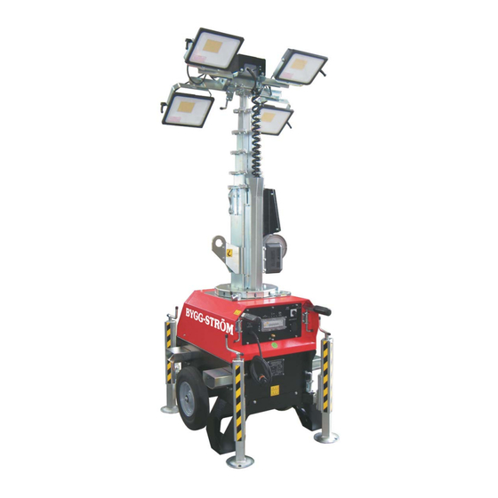
TECHNICAL SPECIFICATIONS LIGHTING TOWER COMPONENTS 1. Floodlight rotating handle 2. Floodlights 3. Telescopic mast 4. Lifting hook with crane 5. Winch 6. Mast release lock pin 7. Bubble level 8. Mast raising / lowering handle 9. Extractable handles 10.Stabilizer raising / lowering handle 11.Stabilizer release lock pin 12.Extractable stabilizers 13.Fork‐lift pockets 14.Data plate Manual Code - MI400A00105 Revision Level 00 - 09/09/2019 10 ... -
Page 11: Machine Controls
TECHNICAL SPECIFICATIONS MACHINE CONTROLS Control panel AUTO MODE MANUAL MODE LAMP LIGHT PROTECTION SENSOR 230 V OUTLET POWER INLET 1) 230V 16A Mains inlet 2) 13A RCD protection 3) Floodlights switches 4) Light sensor 5) Operation mode selector switch 6) 230V 16A Shuko Power outlet 7) Earthing terminal Manual Code - MI400A00105 Revision Level 00 - 09/09/2019 11 ... -
Page 12: Lighting Tower Positioning
LIGHTING TOWER POSITIONING When choosing a location for the lighting tower, bear in mind the following: ‐ Assess site conditions carefully before positioning and operating the machine. ‐ The working area should be relatively level and solid. This will ensure smooth, trouble‐free telescoping of the mast. (which may not telescope properly if the unit is not level.) ‐ Do not position the tower in the vicinity of overhead cables or power lines! ‐ Never raise the mast or operate the tower without properly jacking the unit! ‐ For maximum light coverage and illumination efficiency, locate the unit at ground level or in a spot higher than the area being illuminated by the lamps. ‐ Do not move the tower with the mast raised! HANDLING AND TRANSPORT HANDLING AND MANUAL TRANSPORTATION Hold the extendable handle with one hand and pull the locking pin to release it. Pull the handle outwards until it’s fully extended and ensure that the locking pin locked it in place securely in the extended position. Move slowly and position the machine where needed. Manual Code - MI400A00105 Revision Level 00 - 09/09/2019 12 ... -
Page 13: Handling And Transport With Crane
HANDLING AND TRANSPORT HANDLING AND TRANSPORT WITH CRANE Handling by crane is allowed only if the machine is connected to the crane through the lifting eye. (C) Ensure that the lifting capacity of the crane and lifting devices is suited to the weight of the machine to move. The weight is specified in the provided documentation (user’s manual) and on the data plate. Connect the cable/hook to the lifting eye (D) and tension the cable. Lift the machine for about 10 cm (4 in.). Move slowly and position the machine on the ground or on the vehicle. HANDLING AND TRANSPORT WITH FORKLIFT Ensure that the lifting capacity of the forklift is suited to the weight of the machine to move. The weight is specified in the provided documentation (user’s manual) and on the data plate. Insert the forks into the forklift pockets (E). Lift the machine for about 10 cm (4 in.). Move slowly and position the machine where needed. Manual Code - MI400A00105 Revision Level 00 - 09/09/2019 13 ... -
Page 14: Lighting Tower Use
LIGHTING TOWER USE STABILIZING THE UNIT The stabilizers are extendable (F) and (G). Jack up the unit as follows. Hold the stabilizer with one hand and pull the locking pin to release it. Pull the stabilizer outwards until it’s fully extended and ensure that the locking pin locked it in place securely in the extended position. Jack the unit up by rotating the handle on the top of each stabilizer clockwise. Please refer to the bubble levels (H) installed on top of the machine (near the mast) in order to have the machine perfectly leveled and stable before rising the tower. The wheels of the machine have to touch the ground at all times. DIRECTING THE FLOODLIGHTS The tower can be rotated up to 340 degrees in order to direct the light as required. Release the rotation locking pin (I) and turn the tower using the rotation handles on the mast in order to direct the lights as needed. Don’t forget to lock the rotation afterwards. Additionally to the mast rotation, each of the LEDs can be adjusted on two axes and tilted back and forth. This way the lights can be directed either vertically or horizontally. In order to adjust the light on the vertical axes, the encircled pin (L) needs to be unlocked by pulling it and then turning the floodlight. For any adjustments, the mast must be lowered to allow access. ... -
Page 15: Preliminary Check
LIGHTING TOWER USE PRELIMINARY CHECK Before operating the unit, we suggest making the following routine checks for improved safety, better efficiency, longer product life and in order to avoid work disruptions. Check that the machine is leveled correctly and stabilized firmly. Check that all the lamp lenses are clean and undamaged. After adjusting the lights, prepare to raise the tower by: Inspecting the cable and replacing it, if damaged. Checking mounting hardware for proper tightness and re‐torquing if necessary. Raise the mast and insert the safety pin supplied in the appropriate hole, see picture. Ensure that all the electrical cables are undamaged and correctly connected. Check that the main switch and the lamps switches are in the OFF position. Drive the earth picket into the ground (earth) following any risk assessment. (*) Check that the grounding cable is securely attached to the unit. Open the frontal door to access the control panel. For operators’ safety, the grounding of the machine always needs to be done paying attention on the section of the cable to be used (never to be less than 10 mm2). For the connection of the grounding cable, please always use the clip located on the control panel, on the right side of the machine. Always perform grounding operations in compliance with local/international regulations. -
Page 16: Manual Mode
LIGHTING TOWER USE MANUAL MODE AUTO MODE MANUAL MODE LAMP LIGHT PROTECTION SENSOR 230 V OUTLET POWER INLET Connect an electrical supply to the plug (1). Make sure that the power line is protected by an appropriate differential switch and main switches. Use the electrical outlet (5) to connect another unit. Turn the selector switch (4) in “Manual Mode”. Switch on the lights using the switch (2). To turn off the lamps, turn the light switch (2) and the selector switch (4) to OFF. LIGHT SENSOR MODE Connect an electrical supply to the plug (1). Make sure that the power line is protected by an appropriate differential switch and main switches. Use the electrical outlet (5) to connect another unit. Turn the selector switch (4) in “AUTO MODE”. Set the light sensor (3) to a value between min. 25 and Max. 70. Switch on the lights using the switch (2). ... -
Page 17: Routine Maintenance
ROUTINE MAINTENANCE Poorly maintained equipment can become a safety hazard. In order, for the equipment, to operate safely and properly over a long period of time, periodic maintenance and occasional repairs are necessary. Any kind of maintenance work on the lighting tower must be carried out by Authorized and trained personnel. It should be done in a safe working environment and with the machine well stabilized. The engine must be turned off and let cool down sufficiently before starting to work on it. While performing maintenance work, please use suitable tools and clothes. DO NOT modify any component if not authorized. The repairs cannot be considered among the routine maintenance activities. E.g. the replacement of parts that are subject to occasional damage and the replacement of electric and mechanic components that wear with use. This kind of work is not –in fact‐ covered by warranty. ... - Page 18 Manual Code - MI400A00105 Revision Level 00 - 09/09/2019 18 ...
-
Page 19: Spare Parts
SPARE PARTS Manual Code - MI400A00105 Revision Level 00 - 09/09/2019 19 ... - Page 20 SPARE PARTS Manual Code - MI400A00105 Revision Level 00 - 09/09/2019 20 ...
- Page 21 SPARE PARTS N. CODE DESCRIPTION 1 AC000_M000_086 CLOSING LOCK PIN 2 PFM07_C000_040ZN ROTATION PLATE 3 PFM07_C000_043ZN PLATE 4 PFM07_C000_018 HANDLE SUPPORT PLATE 5 AC000_M000_076 HANDLE M10x40 6 PFM07_C000_039ZN CENTRAL FRAME 7 AS000_M023_025 SPACER 8 AC000_M038_007 RUBBERIZED HOSE CLAMP LED04_C000_129ZN BRACKET FOR LED FLOODLIGHT (100W) 9 LED04_C000_143ZN BRACKET FOR LED FLOODLIGHT (200W) 10 AC000_M000_036 FLOODLIGHT HANDLE 11 ‐‐‐‐‐‐ LED 100W FLOODLIGHT 13 ...
- Page 22 SPARE PARTS Manual Code - MI400A00105 Revision Level 00 - 09/09/2019 22 ...
- Page 23 SPARE PARTS N. CODE DESCRIPTION 1 PFM08_C031_061 ROTATION FLANGE 2 PFM07_C000_022ZN LIFTING EYE ASSEMBLY, RIGHT PART 3 PFM07_C031_075ZN 1° SECTION MAST 4 PFM07_C031_070 MAST SUPPORT 6 AC000_M000_084_01 WINCH HANDLE 7 AC000_M000_084 WINCH BODY 8 PFM08_C031_062ZN MAST ROTATION POSITIONING DEVICE, LEFT 9 AS000_M000_029 SCREW 10 PFM08_C000_047 COILED CABLE BOTTOM PLATE 11 PFM07_C000_037 COILED CABLE PROTECTION 12 AC000_E006_016 COILED CABLE 13 PFM08_C000_018 FRONT COVER ...
- Page 24 SPARE PARTS Manual Code - MI400A00105 Revision Level 00 - 09/09/2019 24 ...
- Page 25 SPARE PARTS N. CODE DESCRIPTION 1 AC000_M038_044 NUT 2 AC000_M000_038 WHEEL 3 LUX C12_C003_033 WHEELS AXLE 4 LUX C12_C000_034 SUPPORT FRAME 5 LUX C12_S010_051B DATA PLATE 6 LUX C12_C000_031ZN STABILIZER BEAM 7 AS000_M000_048ZN STABILIZER 8 LUX C12_C004_030 BASE FRAME 9 LUX C12_C000_036 ANTIROTATION HOLDER 11 LUX C12_C007_035 CANOPY 12 AC000_M000_086 LOCK WITH PIN 13 AC000_P037_003 RUBBER HANDLE ...
- Page 26 SPARE PARTS N. CODE DESCRIPTION 1 AC000_E006_041 SELECTOR 2 AC000_E000_070 CAPACITOR 3 LUX C12_C006_044 CIRCUIT BREAKERS FRAME 4 AC000_E011_016 OUTLET SHUKO SOCKET 16A ‐ 230V 5 AC000_M038_035 EARTHING CLIP 6 AC000_E000_008 CIRCUIT BREAKER PROTECTION 7 AC000_E018_007 WIRE HOLDER 8 LUX C12_S010_059B FRONT PLATE 9 AC000_E012_028 13A RCD 10 LUX C12_C006_076 CIRCUIT BREAKERS SUPPORT 11 AC000_E012_027 LAMP SWITCH 12 ...
-
Page 27: Electrical Diagram
ELECTRICAL DIAGRAM Manual Code - MI400A00105 Revision Level 00 - 09/09/2019 27 ... - Page 28 ELECTRICAL DIAGRAM Manual Code - MI400A00105 Revision Level 00 - 09/09/2019 28 ...
- Page 29 ELECTRICAL DIAGRAM Manual Code - MI400A00105 Revision Level 00 - 09/09/2019 29 ...
-
Page 30: Warranty
WARRANTY The warranty period Starts on the delivery date to the first purchaser. The machine is covered by warranty for 1 year from the above mentioned date. Only genuine parts should be used to carry out repairs. Failure to use only genuine parts may invalidate the manufacturer’s warranty. The company reserves the right to request the warranty replaced parts back for analysis. All engine warranty issues must be directed to the engine manufacturer, or the manufacturer’s approved engine dealer. The company will not be held responsible if: ‐ the machine has been used to perform tasks that it has not been designed for; ‐ the machine has undergone modifications not approved by the company; ‐ conditions of use have been abnormal; ‐ normal maintenance, compliant to requirements as set out by the manufacturer, have not been adhered to. No payment or expenses refund should be pretended from the manufacturer for normal maintenance or servicing nor any materials used to carry out routine servicing. The warranty is intended to cover diagnosis, repair or replacement of the defective part, and actuating the repair, should a problem arise during the warranty period. These operations will be performed free of charge. Manual Code - MI400A00105 Revision Level 00 - 09/09/2019 30 ...
Need help?
Do you have a question about the LUX C12 and is the answer not in the manual?
Questions and answers