Table of Contents
Advertisement
"Built-Better/Backed-Better Warranty"
All Texwrap manufactured components are warranted against defects in design, material and
workmanship for a period of three (3) years- unlimited cycles. All purchased components are
warranted for a period of one year. Warranty is transferrable for the life of the Warranty
beginning with date of shipment to the original purchaser's facility. Warranty does not cover
the replacement of consumable/wear items (sealing blades, sealing pads, tape, belts, etc),
routine maintenance, or alignments.
Texwrap will, at their discretion, repair or replace a defective component at no charge
including UPS ground transportation. Field technician labor is typically handled on
warranted items by local Texwrap distributors on a billable basis. Contact your local
Texwrap distributor for their warranty claim procedure and policies.
This warranty will become null and void if it is determined by Texwrap that:
- the equipment is misused, abused or neglected in any way.
- the equipment is altered or modified without prior written approval from Texwrap.
Texwrap does not warrant that the equipment conforms to any insurance regulation, electrical
or safety code (with the exception of panels containing UL stickers, which meet UL codes).
The purchaser assumes liability for compliance with all applicable statutes, codes and
regulations whether federal, state or local.
This limited warranty applies only to the repair or replacement of defective parts. Warranty
does not cover replacement parts not purchased from Texwrap.
For any replacement part shipped under warranty, the defective part must be returned to
Texwrap by a Texwrap distributor within 30 days for examination. If determined to be
defective, a credit will be issued. If the part is determined not to be defective, the part will be
returned to shipper and no credit issued. Credits will not be issued for parts after 30 days.
Please note: A Return Authorization (RA) number must be obtained from the Parts
Department prior to shipment of a defective part to Texwrap.
Confidential and Proprietary
Rev. 10.06
Texwrap
2.3
Advertisement
Table of Contents

Summary of Contents for TEXWRAP 2219 Series
- Page 1 (sealing blades, sealing pads, tape, belts, etc), routine maintenance, or alignments. Texwrap will, at their discretion, repair or replace a defective component at no charge including UPS ground transportation. Field technician labor is typically handled on warranted items by local Texwrap distributors on a billable basis.
- Page 2 This page intentionally left BLANK...
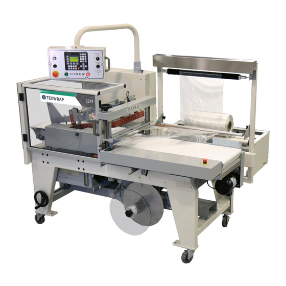
- Page 3 The TEXWRAP model 2219 is a horizontal form, fill and seal. The L-Sealer seal head is pneumatically operated, with all other functions performed with VFD AC motors. All moving parts have been covered with safety interlocked guards so as to keep the user safe.
- Page 4 INSTALLATION REQUIREMENTS Wrapper must have dedicated, hard wire drop circuit 240 VAC single phase, 20 Amp, with local disconnect capabilities. All connections must be properly grounded from circuit box, with earth ground origin. Compressed air line capable of 80PSI, 2CFM – clean, dry air. There should be a minimum clearance of 6ft.
- Page 5 FILM ROUTING 1. Align roll of film so that edge is slightly in front of inverter point, follow thread diagram. Set tracking roller so that equal tension is applied to top and bottom inverters. 2. Thread film over inverting heads, note conveyor removed to show process; red back with white interior. Separate laps of film with anti-static tinsel bar.
- Page 6 SCRAP ROUTING 1. Place film between puller chains to begin scrap tail. Use manual jog and seal to create tail. Route around rollers and tie onto spooler. NOTICE: Machine ships with spool assembly removed. Use above picture for assembly aid.
-
Page 7: Table Of Contents
Constant Run Conveyor..................27 Belt Reversing....................28 Pass Thru Mode ....................28 Service.......................29 Tune Heater...................30 PLC Inputs/Outputs ................31 Counters ....................32 Set Time, Date & View.................32 Texwrap ....................33 Test Mode ................33 Program Library.......................34 Machine Alarms/Error Correction ...................38 Maintenance........................39 Conveyor Belt Tracking....................40 Film Clamp Safety ......................41... - Page 8 This page intentionally left BLANK...
- Page 9 TEXWRAP 2219 OPERATIONS MANUAL...
-
Page 10: Control Panel Layout
Machine Interface This Texwrap model features a swivel user interface with touch-pad control. All controls and electrical settings can be modified by the user through this interface. Touch-pad Interface Machine Reset Button Selectable seal eyes switch Door Open Manual Seal... -
Page 11: Touch-Pad Quick Access Buttons
TOUCH PAD PANEL QUICK ACCESS BUTTONS Change Security Level Access Heater Settings Front & Rear Bag Timers Product Counter Reset Manual Jog (Press and Hold) Manual Seal Seal Time Set-ups Library (Press and Hold) Manual Jog and Manual Seal – Press and hold these buttons to activate. Manual Seal will only work with the seal area door closed, otherwise use the two hand seal buttons. -
Page 12: Home Screen
HOME SCREEN Display of current security level View active and history of alarms Products per minute display Product count Silence Alarms display Press to go back in Display of previous screens. temperature settings Press to display Menus. Press this button at any time to return to this screen (Home). -
Page 13: Front And Rear Bag Settings
Front and Rear Bag Settings Front Bag Timer Front bag is the amount of bag in front of the package. When the Run button is pressed, or after each seal cycle, this will be the amount of film pulled. Press the PREV (UP) or NEXT (DOWN) button to highlight the setting to change. The user may press the RAISE or LOWER button to adjust the value, or type in a desired setting. -
Page 14: User Level
User Levels Texwrap offers 3 levels of security for the customer. OPERATOR – This level gives the least amount of access, only allowing a program to be loaded, manual jog and seal, and alarm clearing. SETUP – Allows access to every setting accept the service screen. -
Page 15: Heater Settings/ Seal Time
Heater Settings Press the PREV (UP) or NEXT (DOWN) button to highlight the setting to change. The user may press the RAISE or LOWER button to adjust the value or to ENABLE/DISABLE a desired setting. When done press ENTER. To return to the previous screen press the EXIT button. To return HOME, press the center button directly below the display screen. - Page 16 This page intentionally left BLANK...
-
Page 17: Machine Menus
MENUS When the MENU button is pressed, Menu #1 screen will be displayed. To access the screen of the item desired, press the number on the keypad corresponding to the label. To access the next menu, press the number 7 on the keypad. Pressing the MENU button repeatedly will also scroll through the Menu screens. MENU #1 MENU #2 MENU #3... -
Page 18: Motion Trims
Motion Trims TEXWRAP MOTION TRIMS The purpose of this feature is to increase the throughput of any certain product. This is accomplished by starting the opening or closing action of the seal bar before the staging eyes tell the machine to do so. -
Page 19: Tail Remover
Tail Remover The purpose of this feature is to help remove the corner strip of film that sometimes develops in the corner of the ‘L’ seal. This is accomplished by stopping the film pull chains and keep the outfeed conveyor running (for the specified amount of time) to turn the product slightly. -
Page 20: Scrap Alarm
Scrap Alarm As the machine runs, the scrap spool cycles on and off rolling up the scrap stream. This is done by running the spool until the dancer arm hits the switch, which stops the spool allowing the arm to drop again. -
Page 21: Hole Skip
Hole Skip Some products being packaged are not always solid from front edge to rear edge. This feature allows the user to enter an amount of time for the staging eyes to ignore small gaps in the product or reflections off of the film, so that the product is treated as a complete unit. -
Page 22: Hole Punch
Hole Punch These parameters are for control of a pneumatic punch. Additional equipment will be necessary to use this feature. Press the PREV (UP) or NEXT (DOWN) button to highlight the setting to change. The user may press the RAISE or LOWER button to adjust the value or to ENABLE/DISABLE a desired setting. Press ENTER when done. -
Page 23: Front Edge Trip
Front Edge Trip Use this feature if the rear of the package is indefinable (not a straight edge). First turn the feature ON/OFF by pressing the RAISE or LOWER button. Next adjust the Rear Bag timer to a large enough time to allow the package plus rear bag to enter the seal area. -
Page 24: Seal Compensation
Seal Compensation As the machine cycles, the seal pad will begin to warm up from coming in contact with the hot seal knife. When the seal pad warms up to a certain amount, the seal time necessary to make a good seal diminishes. The Seal Compensation parameter allows the cycle time to slightly increase based off of observations of the seal time and amount of time required to heat up the seal pad. -
Page 25: Multi-Pack
Multi-Pack The 2219 can multi-pack a single row of items to the extent of the side seal area. It performs this by indexing product into the seal area, one at a time, pushing them back-to-back. When the number entered is achieved, the seal bar will close. A setting of “01” is a single package. To return to the previous screen press the EXIT button. -
Page 26: Print Registration
Print Registration These parameters are for use with printed film. Additional equipment will be necessary to use this feature. Press the PREV (UP) or NEXT (DOWN) button to highlight the setting to change. The user may press the RAISE or LOWER button to adjust the value or to ENABLE/DISABLE a desired setting. Press ENTER when done. -
Page 27: Upstream Conveyor
Upstream Conveyor This feature is for the control of a feeder conveyor. When wired properly, this can start and stop the conveyor with the seal head (Indexing ON) or let the conveyor run continuously (Indexing OFF). Turn the feature ON/OFF by pressing the RAISE or LOWER button. To return to the previous screen press the EXIT button. -
Page 28: Belt Reversing
Belt Reversing This feature will reverse the exit for a desired period of time, thus relaxing the film prior to the seal bars closing. Pass Through Mode Turn the feature ON/OFF by pressing the RAISE or LOWER button. This turns all machine functions off except the conveyors, turning the machine into one conveyor so that the line configuration does not have to change for differing production needs. -
Page 29: Service
Service Press the corresponding number to access the desired screen... -
Page 30: Tune Heater
Tune Heaters Press the button directly below the label of the heater desired to tune. The display will show that the heater is tuning. Nothing else is needed, the tuning will stop automatically when it is finished. The heaters need to be tuned only if a heater element or thermocouple has been changed. However it will not hurt anything if it is done without any change. -
Page 31: Plc Inputs/Outputs
PLC Inputs / Outputs For aid in troubleshooting, the 2219 has a list of the inputs and outputs. It will display which ones are on and off. If the input or output seems to not be showing properly, there may be a communication lag. Check PLC lights as these will always be correct. -
Page 32: Counters
Counters This screen displays the total cycles the machine has made and the number of cycles since the last time the “Reset PM Counter button was pressed. Set Time, Date and View Press the PREV (UP) or NEXT (DOWN) button to highlight the setting to change. The user may press the RAISE or LOWER button to adjust the value, or type in a desired setting. -
Page 33: Texwrap
Texwrap To turn the “Test Mode” feature ON/OFF press the RAISE or LOWER button Press the PREV (UP) or NEXT (DOWN) button to highlight the setting to change. The user may press the RAISE or LOWER button to adjust the value, or type in a desired setting. When done press ENTER. -
Page 34: Program Library
PROGRAM LIBRARY The purpose of program library is to store the Electronic machine settings for a particular product. This allows you to store a program for your product, give it a name or code and recall it any given time. After the operator selects the program to run, and adjusts any physical items, you will be ready to start production of that product. - Page 35 Save Setups Cont’d Step 3: If the setup is to be saved as a new name, the following screen will appear. Enter a name, press ENTER and then press the button below the SAVE label to initiate the save. NOTE; a name must be entered, limited to 8 characters, no spaces, and the file name must be different than one already in the library.
- Page 36 To LOAD a setup, follow these steps. Step 1: Press number 2 on the keypad for Select File to Run. Step 2: If number 2 is pressed, the Load Existing File screen will appear. On this screen, press the up/down arrows to scroll to the desired file to load and press the button under the LOAD label.
- Page 37 To DELETE a setup, follow these steps. Step 1: Press number 3 on the keypad for Manage Library. Step 2: If number 3 is pressed, the Delete Saved Files screen will appear. On this screen, press the up/down arrows to scroll to the desired file to delete and press the button under the DELETE label.
-
Page 38: Machine Alarms/Error Correction
ERROR SCREENS & SOLUTIONS Press this button to view past and present alarms. If an error occurs that triggers an alarm, the screen will flash a message saying what the error is. Press the alarm button to view a list of the current and past alarms. Once the error is fixed, RESET will clear the error. -
Page 39: Maintenance
Texwrap recommends the following maintenance schedule. Recommended Maintenance Schedule: Daily: 1. Check the silicon pad beneath the seal bars for wear. Replace if necessary. 2. Check conveyor belts for proper tension and tracking. 3. Look under and inside conveyors for any scrap bags. Remove and discard. -
Page 40: Conveyor Belt Tracking
CONVEYOR BELT TRACKING A daily glance at the conveyor belts for proper tracking is recommended. Sometimes a change in product size or weight can cause shifts in belt tracking. If any of the belts have drifted to the edge of the conveyor, adjustments are necessary. -
Page 41: Film Clamp Safety
Each Texwrap sealer machine is shipped with a “Safety Tester” (Part # 80-SAFETYTEST) this is used to properly set-up and test the film clamps. The film clamps should always be tested before the machine is to be operated. - Page 42 2. With the tester in place remove the lock out, press the reset button and simulate a manual seal. AVOID INJURY DO NOT HOLD THE TESTER IN PLACE WITH YOUR HANDS OR FINGERS DURING THE SEAL CYCLE. When the machine attempts to cycle, the seal head should instantly open upon striking the safety tester and the machine should go into an e-stop mode.
- Page 43 Adjusting the Film Clamp Safety Switches Step 1 Remove air from the machine by turning the air dump valve clockwise. Step 2 Close the seal bars until the film clamps are resting on the seal pad. (The entire cross and side film clamps must be evenly in contact with the pad).
- Page 44 • Check the film clamp safety switches. They may be set too low and not tripping when they should. • Also check the seal bar position prox, it may be set too low and activating before the film clamps hit the safety tester. If the problem continues DO NOT OPERATE THE MACHINE contact your Texwrap distributor.
- Page 45 ITEM NO. PART NUMBER DESCRIPTION QTY. 80-ES081B ENCLOSURE, CONTROL PANEL FACE PLATE 2219 NEW - 75-ES087 CONVEYOR SPEED 80-ES084 PANEL, COVER 75-E023G SWITHC, ESTOP N/C 75-E020GDC SWITCH, GREEN LIGHT 75-E007GDC SWITCH, RED LIGHT 75-E006GDC SWITCH, RESET, WHITE LIGHT SWITCH, SS, 3P, 1NC-1NO, CS 75-E012G EYES 70-07793...
- Page 46 ITEM NO. ITEM NO. PART NUMBER PART NUMBER DESCRIPTION DESCRIPTION QTY. QTY. 80-ES071B 80-ES071B ENCLOSURE, ELECTRICAL ENCLOSURE, ELECTRICAL 70-07760 70-07760 HINGE HINGE 80-ES085-A 80-ES085-A DOOR, ELECTRICAL DOOR, ELECTRICAL 80-ES077A 80-ES077A PLATE STIFFENER PLATE STIFFENER 70-07761 70-07761 LATCH, 146 ENCLOSURES LATCH, 146 ENCLOSURES 20-00290A 20-00290A NAME PLATE/ POWER OUTPUT...
- Page 47 ITEM NO. ITEM NO. PART NUMBER PART NUMBER DESCRIPTION DESCRIPTION QTY. QTY. 80-ES073-B 80-ES073-B SUB PANEL, 2219 AC STYLE SUB PANEL, 2219 AC STYLE 20-02033 20-02033 GROUND LUG ALUMINUM GROUND LUG ALUMINUM 20-02086 20-02086 FUSE, 3A, 600V, ATDR FUSE, 3A, 600V, ATDR 20-02156UL 20-02156UL POWER SUPPLY, 24VDC...
- Page 48 ITEM NO. PART NUMBER DESCRIPTION QTY. 80-OC050 SIDE PLATE (FRONT) 40-00401 5/8" FLANGED BEARING 75-IC032GA-A ROLLER, DRIVE 80-CC042A-A CYLINDER SUPPORT BAR -B 80-CC041A-A CYLINDER SUPPORT BAR -A 80-IC027GA IDLER AXLE 80-OC014GA SUPPORT SHAFT 80-OC053 AXLE, ADJUSTING 50-05659 BELT, TRANSFER CLOSURE 80-OC051 DECK, FIXED 80-OC052...
- Page 49 ITEM NO. PART NUMBER DESCRIPTION QTY. 80-OC016C ADJUSTING ROD 80-IC035 IDLER AXLE ROLLER, IDLER CROWNED, W- 80-IC033C BRGS 80-IC036 CROWNED IDLER ROLLER 40-00463 THRUST BEARING 40-04010 BEARING, LINEAR SLIDE 80-IC027GA IDLER AXLE 40-00425 1/2" THRUST WASHER 80-CC029C-A SLIDING SIDE PLATE 80-CC003C-A SLIDING SIDE PLATE 80-CC002C-A...
- Page 50 ITEM NO. PART NUMBER DESCRIPTION QTY. 80-FA027C-A FRONT INFEED SLIDE PLATE BRG, SLIDE, ASSY, 2-PAD, 40-00427 700MM, THK 80-FA047A-B SIDE COVER, 2219 80-FA028G COVER STUDS E-STOP, RED MUSHROOM, 75-E021G RETAIN, 1NC 20-02415 ESTOP HIGHLIGHT RING 60-06720 ASSEMBLY, NEEDLE VALVE 80-ACC06-2 BRACKET, VERTICAL SLIDING 20-02584 SENSOR, FILM REGISTER...
- Page 51 41 42 41 42...
- Page 52 ITEM NO. ITEM NO. PART NUMBER PART NUMBER DESCRIPTION DESCRIPTION QTY. QTY. 80-FS087 80-FS087 FILM STAND FRAME FILM STAND FRAME 40-00400 40-00400 BEARING, 1/2" PEER, FLANGED BEARING, 1/2" PEER, FLANGED 40-00401 40-00401 5/8" FLANGED BEARING 5/8" FLANGED BEARING 80-FS008G 80-FS008G ROLLER STOPPER SHAFT ROLLER STOPPER SHAFT 20-02311AC...
- Page 53 ITEM NO. PART NUMBER DESCRIPTION QTY. 80-FS078 BRACKET, ROLLER 80-FS077 BRACKET, ROLLER 80-00702 ROLLER, IDLER W/BRGS 75-FS059G PIN PERF RING CLLR, SET, 1.000" B , 1 PC, SPLT, 40-04032 80-07781-104 BRUSH, PERF BACKUP 80-FS005G SHAFT FOR PIN PERFS & IDLERS 40-00423 CLLR, SET, 0.250"...
- Page 54 ITEM NO. PART NUMBER DESCRIPTION QTY. BRACKET, FILM SEPERATOR, 80-FS079 LEFT 80-FS063G FILM SEPERATOR SHAFT 30-00302 KNOB, #10-24 MALE 80-FS080 BRACKET 80-00702 ROLLER, IDLER W/BRGS 80-FS005G SHAFT FOR PIN PERFS & IDLERS 40-00423 CLLR, SET, 0.250" B , 1 PC...
- Page 55 ITEM NO. ITEM NO. PART NUMBER PART NUMBER DESCRIPTION DESCRIPTION QTY. QTY. 80-FS082 80-FS082 PRESSURE ROLLER PIVOT AXLE PRESSURE ROLLER PIVOT AXLE 80-MPU077 80-MPU077 ROLLER, DRIVE PRESSURE ASSY ROLLER, DRIVE PRESSURE ASSY 80-MPU075 80-MPU075 PRESSURE ROLLER AXLE PRESSURE ROLLER AXLE 80-MPUR015 80-MPUR015 PRESSURE ROLLER ARM...
- Page 56 ITEM NO. PART NUMBER DESCRIPTION QTY. 80-FF117-1 SENSOR BRKT BRACKET ARM, SENSOR 80-FF116-1 MOUNT 80-ACC07-1 PLATE, NUT CLAMP 30-00301 KNOB, 1/4-20, MALE 20-02584 SENSOR, FILM REGISTER...
- Page 57 ITEM NO. PART NUMBER DESCRIPTION QTY. GUARD DOOR SUPPORT 80-GS001E FRAME 75-GS030A REAR COVER MACHINE (AC) 70-07760 HINGE 75-GS003C SEAL HEAD DOOR 70-07793 HANDLE 80-GS019C-A GUARD SWITCH, LEFT SAFETY 20-02306 INTERLOCK 80-GS028 BRKT, SWITCH MOUNT 70-07700 LATCH, GRAB NUT PLATE, SAFETY SWITCH & 80-GS048 LATCH 20-02306-KEY...
- Page 58 ITEM NO. PART NUMBER DESCRIPTION QTY. 80-IC018C-AZ INFEED SIDE PLATE REAR, LH 80-IC016GZ MOUNTING BRACKET 80-IC034C-A INFEED SIDE PLATE FRONT 80-IC022AZ CONNECTING ANGLE 80-IC021A INFEED SUPPORT BAR 80-IC029A CONNECTING BAR 80-IC023AZ SUPPORTED SIDE BAR 80-IC039A SPACER BAR 80-IC019AZ UNDER TRAY, INFEED CONV 80-IC037A BRACE 80-IC027GA...
- Page 59 Film Inverter Spare Parts List Electrical Enclosure Main Frame Seal Head Assembly To access the parts breakdown of a machine section click on that section Guarding Scrap Winder Exit Conveyor STORK / Texwrap Inc. 525 Vossbrink Dr Washington Missouri 63090...
- Page 60 THE INFORMATION CONTAINED IN THIS DRAWING IS THE SOLE PROPERTY OF STORK-TEXWRAP. Sales Order # Job Order # Serial # MACHINE_SPEC MS-1 ANY REPRODUCTION IN PART OR AS A WHOLE WITHOUT THE WRITTEN PERMISSION OF STORK-TEXWRAP ISPROHIBITED. STORK / Texwrap Inc. 525 Vossbrink Dr Washing ton Missouri 63090 636.239.7424...
- Page 61 ITEM NO. ITEM NO. PART NUMBER PART NUMBER DESCRIPTION DESCRIPTION QTY. QTY. MAIN FRAME, INFEED MAIN FRAME, INFEED 80-MF050-E 80-MF050-E CONVEYOR CONVEYOR CASTER, L-SEALER (2218 & CASTER, L-SEALER (2218 & 70-00722 70-00722 3022) 3022) BRG, SLIDE, ASSY, 1-PAD, BRG, SLIDE, ASSY, 1-PAD, 40-00409 40-00409 300mm, SS...
- Page 62 ITEM NO. PART NUMBER DESCRIPTION QTY. ITEM NO. PART NUMBER DESCRIPTION QTY. 80-CA042C-D MAIN BEAM 80-CA047C CHAIN TENSIONER 40-00401 5/8" FLANGED BEARING 80-SW017G SWING ARM ROLLER SCREW SHAFT-BEVEL GEAR 80-SW027G WEIGHTS 80-CA033C SIDE 80-SW018G SHAFT ROLLER SCREW SHAFT-SPROCKET 40-00418 CLLR, SET, 0.625" B , 1 PC, ZP 80-CA034C ONLY SPKT, CHN, 35BB20H, 0.625"...
- Page 64 Default/ ITEM NO. PART NUMBER DESCRIPTION QTY. 60-06725 CYLINDER, AIR 3.25 BORE X 2"ST TOP JAW SEE PAGE 3 BOTTOM JAW SEE PAGE 4 FILM GUIDE SEE PAGE 5 SPKT, CHN, 35BB20H, 0.625" B, 10-01131 40-00418 CLLR, SET, 0.625" B , 1 PC, ZP 80-SP066C TENSIONER, CHAIN LONG PUSHROD...
- Page 65 ITEM NO. PART NUMBER DESCRIPTION QTY. 80-SH007C-A TOP HEATER FRAME 80-SH003G HINGE SPACER BLOCK 80-SH006C TOP SPACE BAR 80-SH018C LOWER SPACE BAR 80-SH022C SPACER BOSS 80-SH009C FILM CLAMP, INSIDE CROSS 80-SH011C-A FILM CLAMP SPACER 80-SH013G BRACKET, FILM CLAMP SPRING 80-SH017C FILM CLAMP, OUTSIDE CROSS 80-SH021C FILM CLAMP, INSIDE SIDE...
- Page 66 ITEM NO. ITEM NO. PART NUMBER PART NUMBER DESCRIPTION DESCRIPTION QTY. QTY. 80-SH029C-A 80-SH029C-A CUSHION FRAME CUSHION FRAME 50-05041 50-05041 PAD, SILICON RUBBER PAD, SILICON RUBBER 50-05043 50-05043 PAD, SILICON RUBBER PAD, SILICON RUBBER 80-SH038G 80-SH038G LOWER HEATER HINGE FRONT LOWER HEATER HINGE FRONT 70-00706 70-00706...
- Page 67 ITEM NO. ITEM NO. PART NUMBER PART NUMBER DESCRIPTION DESCRIPTION QTY. QTY. 80-SP067C-A 80-SP067C-A CHAIN DRIVE SHAFT CHAIN DRIVE SHAFT 10-01103 10-01103 SPROCKET,15T WITH 1/2"BORE SPROCKET,15T WITH 1/2"BORE 40-00400 40-00400 BEARING, 1/2" PEER, FLANGED BEARING, 1/2" PEER, FLANGED 10-01104 10-01104 SPKT, CHN, 35B17, 0.500"...
- Page 68 ITEM NO. PART NUMBER DESCRIPTION QTY. 80-CA008A ACTUATING ROD (UPPER) 40-00406 ROD END R.H. THREAD 40-00405 BRG, ROD END, LH, 0.44" B...
- Page 69 ITEM NO. PART NUMBER DESCRIPTION QTY. 80-CA009A ACTUATING ROD (LOWER) 40-00406 ROD END R.H. THREAD 40-00405 BRG, ROD END, LH, 0.44" B...
- Page 70 ITEM NO. PART NUMBER DESCRIPTION QTY. 80-CA023C CRANK LEVER 2219, BUSHING 80-CA022C-B ACTUATING SHAFT 80-CA019C REAR ACTUATING LEVER 80-CA026A REAR ACTUATING LEVER 10-00103 BUSHING-POWER LOCK...
- Page 71 ITEM NO. PART NUMBER DESCRIPTION QTY. BAR, LOWER PINCH WHEEL 80-EH055 MOUNT BAR, UPPER PINCH WHEEL 80-EH062 MOUNT BRACKET, PINCH WHEEL 80-EH054 ADJUSTMENT 70-07709 SPRING, FILM CLAMP, HEAVY 50-00502 ROLLER, FILM MISER 80-EH063 ANGLE, FILM MISER MOUNTING BRACKET, FILM MISER 80-EH064 MOUNTING...
Need help?
Do you have a question about the 2219 Series and is the answer not in the manual?
Questions and answers