Advertisement
Quick Links
Advertisement

Subscribe to Our Youtube Channel
Related Manuals for SENSTAR MPS-4100


Summary of Contents for SENSTAR MPS-4100
- Page 1 MPS-4100 Microwave Protection System Product Guide E6DA0102-003, Rev C Third Edition April 27, 2009...
- Page 2 The information provided in this guide has been prepared by Senstar Corporation to the best of its ability. Senstar Corporation is not responsible for any damage or accidents that may occur due to errors or omissions in this manual. Senstar Corporation is not liable for any damages, or incidental consequences, arising from the use of, or the inability to use, the software and equipment described in this guide.
- Page 3 MPS-4100 configuration options - - - - - - - - - - - - - - - - - - - - - - - - - - - - - - - - - - - - -...
- Page 4 Setting up the MPS-4100 Receiver card- - - - - - - - - - - - - - - - - - - - - - - - - - - - - - - - - - 2-23...
- Page 5 MPS-4100 Specifications- - - - - - - - - - - - - - - - - - - - - - - - - - - - - - - - - - - - - - -...
- Page 7 General description The MPS-4100 bistatic microwave system consists of one Transmitter (Tx) unit and one Receiver (Rx) unit. The Transmitter is a Dielectric Resonant Oscillator (DRO) designed to radiate microwave power at 10.525 GHz. This oscillator is pulse modulated (on-off switched at a 50% duty cycle) with a selectable frequency of 3, 4.5, 7.5, 10.5, 18 or 27 kHz.
- Page 8 Antenna elements housed within the Transmitter and Receiver. The maximum range is 183 m (600 feet). The pattern width is proportional to the distance between the Transmitter and Receiver (see Figure 1-4). 1 - 2 • • • MPS-4100 product guide...
- Page 9 Features Operating frequencies and polarization Six selectable modulation frequencies allow multiple sets of MPS-4100 to be used in either a stacked or linear configuration. Selecting different modulation frequencies prevents crosstalk between different units located in the same area. The Planar Linear Array Antenna transmits the microwave signal in either a vertical or horizontal polarization depending on the orientation of the antenna assembly.
- Page 10 Audio output The MPS-4100 Receiver has a built-in audio output that can be used to evaluate signal variations in the detection path. A tone is generated, which corresponds to objects moving within the microwave field. The tone varies in frequency and amplitude according to the disturbance in the microwave field.
- Page 11 MPS-4100 Transmitter MPS-4100 Transmitter The Model MPS-4100 Transmitter consists of two major sub-assemblies, the antenna assembly and the Transmitter circuit board. The antenna assembly is a planar or linear patch array (see Figure 1-3) coupled to a pulse modulated dielectric resonant oscillator located on the back of the antenna.
- Page 12 MPS-4100 Receiver MPS-4100 Receiver The Model MPS-4100 Receiver consists of two major sub-assemblies, the antenna assembly and the Receiver circuit board. The antenna assembly is a planar or linear patch array antenna, with a signal preamplifier and Schottky diode detector located on the rear side.
- Page 13 Figure 1-4 Typical MPS-4100 coverage patterns Large nearby metallic objects such as vehicles, fences and buildings can be detected well beyond the typical detection envelope. Refer to Application note #1, Do’s and Don’ts: a MPS-4100 product guide • • • 1 - 7...
- Page 14 46 to 51 cm (18 to 20 in.) intermediate overlap (continuous coverage) (30 ft.) Figure 1-6 Intermediate overlap (top view) 1 - 8 • • • MPS-4100 product guide...
- Page 15 MPS-4100 installation requirements. Next, determine the locations of the Transmitter and Receiver pairs. Install the mounting posts, conduit and junction boxes in the selected locations. The MPS-4100 can then be mounted, wired and configured. There are two methods of wiring and configuring the MPS-4100 depending on the application.
- Page 16 If there is grass or vegetation in the protected area, it must be kept cut to a maximum of 8 cm (3 in.) in height. An MPS-4100 should not be operated over open water, or where standing puddles will form.
- Page 17 Optimum security Choose a location that will provide optimum security, yet be free from nuisance alarms. Always locate the MPS-4100 inside a fence or controlled access area to prevent nuisance alarms due to random foot traffic, vehicles, or animals. Units should be located away from parallel fences to avoid reflection of the microwave signal off the surface of the fence, and to prevent the possibility of jumping over the protection pattern.
- Page 18 Communications depending on the model installed. All wiring connections are made on removable terminal blocks, which facilitates maintenance and service activities. The MPS-4100 provides dry relay outputs for alarm and tamper that can be wired ® to virtually any alarm sensor with auxiliary inputs, including the OmniTrax ®...
- Page 19 MPS-4100 to the MX-5000 Series Command and Control Center. In the network communication format, a second MPS-4100 can be wired into the Host MPS-4100 as a Slave system. Power feeds from the Host Receiver to the Slave Receiver and Transmitter. The alarm and tamper signals from the Slave Receiver are fed into the Host Receiver.
- Page 20 Figure 2-4 illustrates the DIP-switch conventions, used in this guide. OPEN DIP-switch setting CLOSED DIP-switch setting (OPEN = OFF) (CLOSED = ON) DIP-switch DIP-switch CLOSED CLOSED Illustration Illustration convention convention switch OFF OPEN OPEN switch ON Figure 2-4 DIP-switch conventions 2 - 6 • • • MPS-4100 product guide...
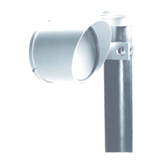
- Page 21 Post mounted MPS-4100 (post side view) Figure 2-5 Post mounting The MPS-4100 requires a stable, permanently anchored mounting post. Mounting posts should be 8, 9, or 10 cm (3, 3½ or 4 inch) O.D. pipe, 1.2 m (4 ft.) high and fixed in a concrete footing.
- Page 22 MPS-4100 (see Figure 2-6). 3. Remove the cover by loosening the 4 captive screws. Pull the cover away and allow it to hang by the strain relief.
- Page 23 Figure 2-6 Mounting post/microwave unit installation For lightning protection and system noise reduction the microwave unit must be connected to a properly installed ground rod using the 1/4x20 screw located on the bottom of the enclosure. MPS-4100 product guide • • • 2 - 9...
- Page 24 2. Set the modulation frequency to the desired channel (1 through 6) via JP1. The Transmitter modulation frequency must match the Receiver modulation frequency. 3. Configure the Tamper notification for conventional relay output or switched power (see Figure 2-8). 2 - 10 • • • MPS-4100 product guide...
- Page 25 Opening the cover interrupts the input voltage and shuts off the transmission of microwave energy, resulting in an alarm condition at the receiver. This option can be used when it is impractical or undesirable to run wiring for the tamper output. MPS-4100 product guide • • • 2 - 11...
- Page 26 To connect the tamper input from the Transmitter to TB2, the Transmitter tamper must be set to NC. 3. Configure the alarm and tamper relay outputs via jumpers JP3, JP4, JP5, and JP6 (see Table 2-2). 2 - 12 • • • MPS-4100 product guide...
- Page 27 1 2 3 4 5 6 LOCAL alarm duration TMPR AUDIO no 3K no 3K TP12 XMTTR DATA/ CONNECT TAMPER AUD PWR TEST TMP ALM ALARM Figure 2-10 MPS-4100 Receiver circuit board MPS-4100 product guide • • • 2 - 13...
- Page 28 Table 2-3 Receiver features Velocity response The MPS-4100 has two jumper-selectable target speeds, Slow and Fast. The default setting is the slow target speed, which is used for detecting human intruders. The fast target speed is used in situations where only vehicles must be...
- Page 29 OFF disables alarm O/P on jam OFF latches alarm relay ON connects Tamper to network O/P ON enables alarm relay S1-6 S2-6 OFF for standard Tamper O/P OFF disables alarm relay Table 2-4 Receiver DIP-switch functions MPS-4100 product guide • • • 2 - 15...
- Page 30 (Toggle S2-5 to reset alarm relay.) Alarm Relay Enable: Enables alarm relay operation for relay output version. May be turned OFF for network operation if local alarm annunciation is not required. 2 - 16 • • • MPS-4100 product guide...
- Page 31 The optional MPS-4100 Communication Interface Card (P/N E6BA010X-003) enables the MPS-4100 Microwave system to communicate via the Silver Network or the StarNeT 1000 network. Installed on header P1 on the MPS-4100 Receiver unit PCB, the card provides redundant network communications through two separate channels (A and B).
- Page 32 Table 2-5 CIC LED functions Software setup For StarNeT 1000 systems, configure the MPS-4100 Microwave System in the StarNeT site database as a PLC-430/IWAVE Transponder by following the directions in the SIMPL Site Creation Guide, J4DA0202 and the Control Program Maintenance Guide, J4DA0402.
- Page 33 • setup the Model MPS-4100 Receiver card for network operation • carefully, plug the card into P1 on the Model MPS-4100 Receiver unit PCB • attach the ground strap to the ground screw on the enclosure MPS-4100 product guide • • • 2 - 19...
- Page 34 Each Silver or StarNeT 1000 network device requires a unique address. Refer to the site plan to determine the network device address assigned to the MPS-4100 Microwave system. For the Silver Network, the address must be between 1 and 32.
- Page 35 Use single point grounding, connect only one side of shield. Figure 2-16 Network communication wiring connections 1. Remove the cover from the back of the MPS-4100 Receiver unit. 2. Route the network communication cables through the conduit port on the back cover.
- Page 36 P1 on the MPS-4100 Receiver card. 1. Connect J2 on the Communications Interface Card to P1 on the Model MPS-4100 Receiver card (see Figure 2-17). (The card must be fully installed onto the header.) 2. Connect the ground strap on the card to the ground screw on the bottom of the Receiver enclosure.
- Page 37 The Receiver card requires shunt and DIP-switch adjustments to communicate on the Silver or StarNeT 1000 networks. The following procedure applies to single system MPS-4100 microwaves, which are connected to Silver Networks or StarNeT 1000 systems. For dual systems, refer to Figure 2-12 for information about Host/ Slave setup.
- Page 38 (see Figure 2-19). Ω Dual Zone (Host/Slave configuration) The first MPS-4100 Receiver/Transmitter pair is designated as the Host system. The second MPS-4100 Receiver/Transmitter pair is designated as the Slave system. The Host Receiver includes the Communications Interface Card, which connects to the network.
- Page 39 2. Connect the Host Transmitter power and tamper pairs to TB2. Power for the Slave Receiver also connects to TB2. The tamper input from the Transmitter must be NC. 3. Install the terminal block and 3 k resistors included in kit E6KT0200 on TB3. MPS-4100 product guide • • • 2 - 25...
- Page 40 O/P to Host Receiver tamper alarm O/P to Host Receiver 12 to 24 VDC I/P from power supply self-test I/P (12 VDC) or from Host Receiver Figure 2-22 MPS-4100 Slave Receiver connections 2 - 26 • • • MPS-4100 product guide...
- Page 41 4. Set the Receiver modulation frequency to match the Transmitter modulation frequency via JP1 and JP2. 5. Configure the operating parameters as a Relay Output version, via S1 and S2 (see Table 2-4). MPS-4100 product guide • • • 2 - 27...
- Page 42 The optional MPS-4100 network transponder enables the MPS-4100 Microwave system to communicate on the MX-5000 multiplex data bus. Installed directly on the MPS-4100 Receiver unit PCB, the card provides network communications through a two wire data bus, which connects to TB1 (Data/Test). One or two Microwave sets can report to the MX-5000 Series Control Center via one transponder card.
- Page 43 JP5, and JP6 (see Figure 2-10). The 3 k EOLR for the tamper circuit should be set Ω at the Slave Transmitter. The return wires for alarm, tamper, audio and self-test may be commoned together. MPS-4100 product guide • • • 2 - 29...
- Page 44 A shielded pair cable for the audio between the Slave and Host Receivers is recommended. The shield should be tied to any Common terminal on TB3 of the Host Receiver only. 2 - 30 • • • MPS-4100 product guide...
- Page 45 • LED 1 on the Communication Interface Card illuminates. • If the alarm display and control System is configured to poll the MPS-4100 System, the Rec A, Rec B and Xmit LEDs will flash intermittently. • Passing your hand in front of the receiver causes a zone 1 detection alarm (Alm1 LED illuminates).
- Page 46 Alignment is easier, faster, and more accurate if done by two people, one at the Transmitter and one at the Receiver. The microwave unit mounting holes in the post mounting bracket are slotted to enable vertical adjustment of the MPS-4100. (Loosen the two screws, adjust the vertical aspect, and re-tighten the two screws.) Horizontal adjustment is accomplished by loosening the bracket’s nut and bolt...
- Page 47 Refer to Do’s and Don’ts a planning primer and Stacking bistatic microwaves for information about installing and aligning the MPS-4100 Microwave system in environments with significant snow accumulation.
- Page 48 Silver Network Test Refer to the product documentation for the alarm display and control system to test MPS-4100 units that communicate over the Silver Network. StarNeT 1000 Test Refer to the Control Program Maintenance Guide, J4DA0402 and the Control Program Operator’s Guide, J4DA0302 for StarNeT 1000 test information.
- Page 49 Beam position TB1 is vertical on the left side of the circuit board. Self-Test function To activate the self-test function for the MPS-4100 Receiver, apply +12 VDC to the self-test terminals on TB1 for at least one second (observe polarity).
- Page 50 Non-detection There are several possible causes for an MPS-4100 Microwave system to be unable to detect valid targets. The following procedure offers suggestions on how to determine and correct these problems. This procedure assumes that the microwave was properly aligned and calibrated before being put into service.
- Page 51 Silver Network/StarNeT 1000 Communication Interface Card The Communication Interface Card includes 12 diagnostic/status LEDs to assist troubleshooting. Test the MPS-4100 according to the directions in the alarm display and control system. Using a two-way radio for communication, have a technician monitor the LEDs on the CIC while an operator conducts the test. If the Communications Interface Card is faulty, power down the card, label and disconnect the network communication cables, and remove the faulty card.
- Page 52 115 VAC, output 13.7 VDC @ 1.2 A with 1 A/h gel-cell battery E6FG0400 (UPS-PFI-2) UPS - input 220-250 VAC, output 13.7 VDC @ 1.2 A with 1 A/h battery 3 - 8 • • • MPS-4100 product guide...
- Page 53 Figure a-1. Microwave units MUST be offset to provide complete coverage of these unprotected areas, as indicated in Figure a-2, Figure a-3 and Figure a-4. MPS-4100 product guide • • • a - 1...
- Page 54 (15 ft.) Figure a-3 Corner overlap top view beam centerline offset - 46 to 51 cm (18 to 20 in.) beam centerline intermediate overlap (30 ft.) Figure a-4 Top view intermediate overlap a - 2 • • • MPS-4100 product guide...
- Page 55 Microwave Series 16000 BW = ZL x 0.055 Microwave Series 24000 BW = ZL x 0.035 BW = beam width ZL = zone length (i.e., unit separation) Approximate beam width relationships MPS-4100 product guide • • • a - 3...
- Page 56 (max.) = BW (beam centerline to nearest limiting object) ÷ numeric factor (product specific) For example, if an MPS-4100 is being installed between two parallel fences that are 6 m apart, the maximum zone length is calculated by dividing 3 m (distance from beam centerline to fence) by 0.066 (MPS-4100 numeric factor), which equals...
- Page 57 DO use microwave offsets and corner overlaps to provide complete coverage of an area, including the transmitter and receiver mounting locations. • DON’T leave vulnerable areas at the transmitter and receiver mounting locations. MPS-4100 product guide • • • a - 5...
- Page 58 2. Check the alignment. For MPS-4100, if the received signal is adequate (LED 6 or greater on the alignment aid, or a voltage measurement of 2.5 VDC at tp6 and tp12) the selected mounting height is correct.
- Page 59 At each transmitter and receiver location, a proper ground rod must be installed according to local electrical codes. The ground rod must be connected to the unit according to the installation instructions. MPS-4100 product guide • • • a - 7...
- Page 60 Figure a-8). This method of stacking microwave sensors can be used to detect bridging attempts made with ladders or other climbing apparatus. This Application Note outlines some of the advantages and disadvantages of stacking the MPS-4100, Series 14000, Series 16000, and Series 24000 microwave sensors. MW Detection zone...
- Page 61 (AGC) to operate closer to the top of its range. This will result in a higher nuisance alarm rate when the microwave path loss increases, for example, during rain or snow. MPS-4100 product guide • • • a - 9...
- Page 62 Mounting height procedure 1. Determine the unit separation in accordance with the detection requirements and clearances (see the MPS-4100 Application Note #1 - DO’s and DON’Ts: a planning primer). 2. For the lower pair, select the mounting height of the center of the antenna from the Recommended mounting heights table.
- Page 63 Stacking bistatic microwaves INCHES MOUNTING HEIGHT UNIT SEPARATION FEET METERS Figure a-10 X-band sensor (MPS-4100, Series 14000, Series 16000) INCHES MOUNTING HEIGHT UNIT SEPARATION FEET METERS Figure a-11 K-band sensor (Series 24000) Heavy snow areas Snow accumulation decreases the effective mounting height. This moves the operating point toward destructive phasing, which could result in degraded performance.
- Page 64 Conclusion For most installations, the mounting height and detection coverage of the MPS-4100 will provide sufficient protection against bridging attempts, as long as the recommendations for zone coverage overlap are followed correctly. When the stacking of bistatic microwave sensors is required, Senstar recommends the use of two MPS-4100 (MPS 4100) X-Band units: •...
- Page 65 The optional MPS-4100 Communication Interface Card P/N E6BA0100-001 (-002) enables the MPS-4100 Microwave system to communicate on the StarNeT 1000 network. Installed directly on the MPS-4100 Receiver unit PCB, the card provides redundant network communications through two removable terminal blocks.
- Page 66 • receives power, ground and alarm data through 21-pin header on the Model MPS-4100 Receiver card • fits in Model MPS-4100 Receiver unit enclosure (no modifications required) • low power consumption • diagnostic LED ON/OFF power switch for reduced power consumption •...
- Page 67 • set up the Model MPS-4100 Receiver card for network operation • plug the card into P1 (XPNDR CONNECT) on the Model MPS-4100 Receiver unit PCB • attach the ground strap to the ground screw Setting the network device address Each StarNeT 1000 network device requires a unique address.
- Page 68 J1 is for the B-side wiring, J3 is for the A-side wiring. For added security, install the network wiring inside conduit. 1. Remove the cover from the back of the MPS-4100 Receiver unit. 2. Route the network communication cables through the conduit port on the back cover.
- Page 69 P1 on the MPS-4100 Receiver card. 1. Connect J2 on the Communications Interface Card to P1 on the Model MPS-4100 Receiver card (see Figure b-5). (The card must be fully installed onto the header.) 2. Connect the ground strap on the card to the ground screw on the bottom of the Receiver enclosure.
Need help?
Do you have a question about the MPS-4100 and is the answer not in the manual?
Questions and answers