
Summary of Contents for Sure-Fi, Inc. Serial Pro DS008-SERIAL
- Page 1 Sure-Fi Serial Pro Bridge Operators Manual Doc #PI0255 Rev 1.0 SURE-FI, INC. | www.sure-fi.com...
- Page 2 Sure-Fi Serial Data Bridge Quick Startup The two units that are packaged together are factory paired and will only communicate with each other. Check initial operation Connect a 9V battery (not included) to the 9V cable (included) and plug the two-position connector into the Serial Data Central Interface and to the Serial Data Remote Interface at the ÄPWRÅ...
-
Page 3: Table Of Contents
Sure-Fi Serial Data Bridge Table of Contents Part Numbers Pg. 5 Overview Pg. 5 Key Features Pg. 5 General Specifications Pg. 6 Radio Transceiver Specifications Pg. 6 Device Overview, Serial Data Central Interface Pg. 7 Device Overview, Serial Data Remote Interface Pg. - Page 4 Sure-Fi Serial Data Bridge Figure Reference Guide Figure 1: Device Overview, Serial Data Central Interface Pg. 7 Figure 2: Device Overview, Serial Data Remote Interface Pg. 8 Table 1: Top Edge Central Connector P1 Pg. 9 Pg. 9 Table 2: Top Edge Central Connector P2 Table 3: Bottom Edge Central Connector P3 Pg.
-
Page 5: Part Numbers
Sure-Fi Serial Data Bridge Part Numbers DS008-SERIAL Serial Data Bridge system: includes 1 ea. SFI-SB501-01 & SFI-SB502-01 SFI-SB501-01 Serial Data Central Interface SFI-SB502-01 Serial Data Remote Interface Overview The Sure-Fi DS008-SERIAL system consists of two factory paired units that are ready to use with no pairing configuration required. -
Page 6: General Specifications
Sure-Fi Serial Data Bridge General Specifications Operating Voltage: 12VDC Operating Current: @ 12VDC: 0.06A (idle), 0.4A (transmit) Operating Power: 4.8 Watt (peak) Battery backup: 12V sealed lead acid (SLA) type only (not included) Battery Low Threshold: < 11VDC Battery Charge Voltage: 13.75V maximum at standby charge Battery Charge Current: Trickle charge, 0.125A maximum at low battery voltage level. -
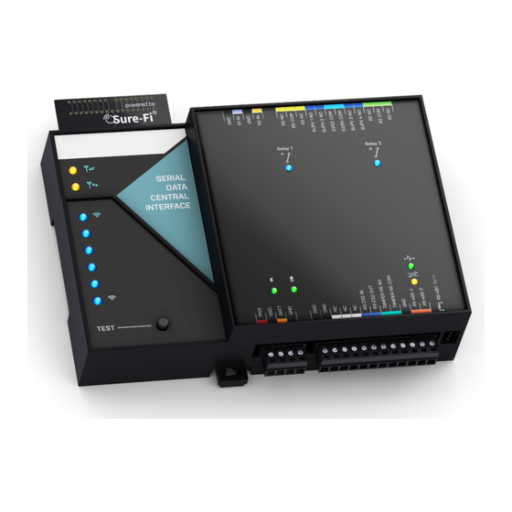
Page 7: Device Overview, Serial Data Central Interface
Sure-Fi Serial Data Bridge Device Overview Figure 1: Overview, Serial Data Central Interface SURE-FI, INC. | www.sure-fi.com... -
Page 8: Device Overview, Serial Data Remote Interface
Sure-Fi Serial Data Bridge Device Overview Figure 2: Overview, Seral Data Remote Interface SURE-FI, INC. | www.sure-fi.com... -
Page 9: Serial Data Central Interface Ç Top & Bottom Connector Pin Descriptions
Sure-Fi Serial Data Bridge Serial Data Central Interface connectors Table 1: Top Edge Central Connector P1. See Figure 1 for connector location and pin numbers CONNECTOR POSITION NAME DESCRIPTION R2 IN Relay 2 control: activates Relay 2 on Serial Data Remote unit DC Ground R1 IN Relay 1 control: activates Relay 1 on Serial Data Remote unit... - Page 10 Sure-Fi Serial Data Bridge Serial Data Central Interface connectors (cont.) Table 3: Bottom Edge Central Connector P3. See Figure 1 for connector location and pin numbers CONNECTOR POSITION NAME DESCRIPTION + DC input - DC input BAT+ Battery backup positive terminal Å+Å connection. 12V SLA type battery only. - DC input Table 4: Bottom Edge Central Connector P4.
-
Page 11: Remote Interface Ç Top & Bottom Connector Pin Descriptions
Sure-Fi Serial Data Bridge Serial Data Remote Interface connectors Table 5: Top Edge Remote Connector P1. See Figure 2 for connector location and pin numbers CONNECTOR POSITION NAME DESCRIPTION R3 IN Relay 3 control: activates Relay 3 on Serial Data Central unit DC Ground R4 IN Relay 4 control: activates Relay 4 on the Serial Data Central unit... - Page 12 Sure-Fi Serial Data Bridge Serial Data Remote Interface connectors (cont.) Table 7: Bottom Edge Remote Connector P3. See Figure 2 for connector location and pin numbers CONNECTOR POSITION NAME DESCRIPTION + DC input - DC input BAT+ Battery backup positive terminal Å+Å connection. 12V SLA type battery only. - DC input Table 8: Bottom Edge Remote Connector P4.
-
Page 13: Providing Power
Sure-Fi Serial Data Bridge Providing Power Each unit requires a 12VDC supply that can source at least 1A. If a Maglock, Door Strike, or other device is to be powered through an on-board wet relay, then the additional power required for those devices will need to be considered when selecting a power supply. -
Page 14: Jumpers Jp1 And Jp2 (Remote Interface Only)
Sure-Fi Serial Data Bridge Jumpers JP1 and JP2 (REMOTE INTERFACE ONLY) Jumpers JP1 / JP2 are used to connect the relay COM terminal to either GND or +VBUS. Connecting the jumper to the +VBUS creates a wet relay contact that can be used to source power to a device. JP1 is for Relay 1, JP2 is for Relay 2. -
Page 15: Relays
Sure-Fi Serial Data Bridge Relays Operating the relays The relay outputs are operated by the corresponding relay inputs that are on the paired unit. For example, to activate Relay 1 on the Remote Interface, the Relay 1 input (R1 IN) on the Central Interface must be shorted to ground (0VDC) using either a dry relay contact, a switch, or a digital voltage 0 to 5VDC interface. -
Page 16: Supervised Inputs
Sure-Fi Serial Data Bridge Supervised inputs The system provides for two fully transparent, four-state, supervised inputs of which the supervision input resistance values are replicated at the Control panel inputs creating an actual wire replacement for these inputs. To use the inputs as supervised inputs, connect two 1K Ohm resistors at the device as shown in Figures 5 and 6 for both Normally-Open (NO) and Normally-Closed (NC) type input devices and wire to the R1 IN or R2 IN inputs on the Serial Data Remote Interface. - Page 17 Sure-Fi Serial Data Bridge Supervised inputs (cont.) At the Serial Data Central Interface, connect a jumper wire and two 1K Ohm resistors as shown in Figures 7 and 8 and wire to the Supervised inputs of the Control panel, then set the inputs as NO or NC type in the Control panel software.
-
Page 18: Antenna, Connector Plug Information
Sure-Fi Serial Data Bridge Antenna The radio antenna is created using copper traces on both sides of the PC Board. Use caution when handling and mounting the unit to ensure that no damage (scratches, etc) occurs to the PC Board/Antenna. Additionally, for best performance, keep cables and wiring away from the antenna and mount the unit oriented with the antenna upwards. - Page 19 Sure-Fi Serial Data Bridge Mounting DIN Rail mount DIN rail mounting allows the unit to easily clip and unclip from the DIN rail. Attach a piece (minimum 5Ñ length) of 35mm type DIN rail to the wall and then snap the unit to the DIN rail or slide it on from the end. The unit will snap in to place by putting the top retaining tabs on to the DIN rail first, then pressing the bottom on to the DIN rail until it snaps in to place, the bottom DIN clip may need to be pressed upward to seat into its locked position.
-
Page 20: Mounting Pg. 19 Ç
Sure-Fi Serial Data Bridge Figure 10: The top screw is shown mounted through the DIN clip to the wall: The bottom screw is shown mounted through the black DIN clip to the wall: Figure 11: SURE-FI, INC. | www.sure-fi.com... -
Page 21: Sure-Fi App Ç Downloading, Installing, Connecting
Sure-Fi Serial Data Bridge Sure-Fi App The Sure-Fi App for iOS and Android allows for firmware updates, configuration and customization as well as for some diagnostics and troubleshooting information. The App is continually being updated to provide for more information and features and to improve its ease of use. To download, search for ÄSure-FiÅ and then download and install. -
Page 22: Sure-Fi App Ç Setting System Heartbeat, Relay Defaults, Timeout, And Alert Relay(S)
Sure-Fi Serial Data Bridge Setting the System Heartbeat time The system Heartbeat is the time interval when the system will automatically perform a system status check if there have not been radio communications between the units during that time. The Heartbeat timer is reset each time any successful transmission occurs between units during regular usage. -
Page 23: Troubleshooting
Sure-Fi Serial Data Bridge Troubleshooting Testing Range and RF communications Press and release the ÄTestÅ button on one of the units and observe the six Signal Strength LEDs. If any of the blue LED 1 through LED 6 lights up momentarily then the transmission between the two units was successful. This establishes that the radio communications between the two units is operational and even with only the LED 1, there is adequate signal strength for proper function. -
Page 24: Fcc And Industry Canada Regulatory Statements
Sure-Fi Serial Data Bridge FCC and Industry Canada Regulatory Statements This device complies with part 15 of the FCC rules. Operation is subject to the following two conditions: (1) This device may not cause harmful interference, and (2) this device must accept any interference received, including interference that may cause undesired operation. -
Page 25: Warranty
Sure-Fi Serial Data Bridge FCC Radiation Exposure Statement This equipment complies with FCC radiation exposure limits set forth for an uncontrolled environment. This equipment should be installed and operated with minimum distance 20cm between the radiator and your body. Important Note: Radiation Exposure Statement: This equipment complies with IC radiation exposure limits set forth for an uncontrolled environment.
Need help?
Do you have a question about the Serial Pro DS008-SERIAL and is the answer not in the manual?
Questions and answers