Table of Contents

Summary of Contents for envea ProGap 2.0-BS Ex
- Page 1 OPERATING INSTRUCTIONS ProGap 2.0-BS (Ex) LEVEL DETECTION WITH FILLING STREAM DETECTION ENVEA - SWR engineering - Gutedelstraße 31 – 79418 Schliengen - GERMANY Tel : +49 (0) 7635 827248-0 / info.swr@envea.global / www.swr-engineering.com...
-
Page 2: Table Of Contents
TABLE OF CONTENTS Page System overview ..........3 Function . -
Page 3: System Overview
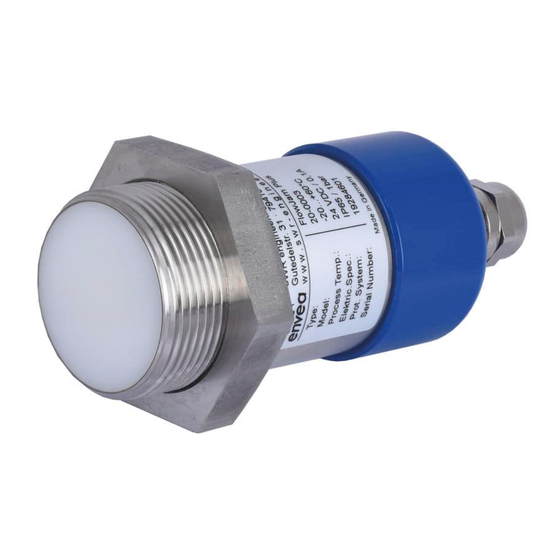
Evaluation unit • Fig. 1: Overview of measuring point: ProGap 2.0-BS Fig. 2: Overview of measuring point: ProGap 2.0-BS Ex 2. Function The microwave barrier is a contact-free measuring method and can be used on both metallic and non- metallic pipes, tanks, shafts, chutes, bellows etc. As non-conductive materials such as plastics are able to penetrate, it can be used for detection from outside or through a window. -
Page 4: Safety
3.4 Technical statement The manufacturer reserves the right to adjust technical data concerning technical developments without • notice. ENVEA - SWR engineering will be delighted to provide information about the current version of the operating manual, and any amendments made. -
Page 5: Mounting And Installation
4. Mounting and installation 4.1 Typical components of a measurement point: G-1½” welded bracket for assembly of the units • 2 x lock nut for locking the units • Process adapter (optional) • Sender unit • Receiver unit • Evaluation unit •... -
Page 6: Mounting Of The Evaluation Unit
For distances longer than 100 m, the cross-section should be adjusted to 1.5 mm Fig. 4: Dimensions of evaluation unit in DIN Rail housing Fig. 5: Dimensions of sender and receiver unit: ProGap 2.0-BS Fig. 6: Dimensions of sender and receiver unit: ProGap 2.0-BS Ex... -
Page 7: Use In Hazardous Areas
Use in hazardous areas Marking DustEx: II 3D Ex tc IIIC T85 °C Dc Voltage range Max. power consumption Power supply (observe type plate) Power supply 1.5 W 24 V DC supplied by evaluation unit Category II 3D Sensor in Zone 22 Housing protection class Sensor = IP65 / evaluation unit = IP40 Safety information for installation in explosive areas... -
Page 8: Electrical Connection
6. Electrical connection The evaluation unit can be installed at a maximum distance of 300 m from the sender and receiver unit. We recommend an insulated, shielded cable with a minimum cross-section of 0.75 mm². From a cable length of 100 m, the cable cross-section must be enlarged to 1.5 mm². -
Page 9: Commissioning
7. Commissioning 7.1 Basic settings Make sure that the transmitter and receiver are installed opposite each other. At distances up to 400 mm, the transmitter should be rotated 90° to attenuate the signal. In addition, a dip-switch is installed in the transmitter via which the sensitivity of the material flow detection can be set. -
Page 10: Menu Structure
7.3 Menu structure Menu point Function Sensitivity of motion detection DP LED lights up: High sensitivity Even small movements are detected DP LED does not light up: Low sensitivity Small movements are ignored Status LED P1 lights up: Motion was detected Switching threshold of motion detection (resolution: 20 levels) DP LED flashes slowly: Reduced switching threshold... -
Page 11: Start-Up Procedure
Polarisation distorted change if necessary Check electrical connection; Display of an “S” on the Sender unit was not detected Contact ENVEA - 7-segment display SWR engineering Check electrical connection; Display of an “E” on the Receiver unit was not detected... -
Page 12: Notes
If the material is not detected, even with an installation on the same side, a special attenuation foil can be • obtained from ENVEA - SWR engineering. Process adapters are essential to use this foil. In case of distances below 400 mm, we recommend rotating the sender or receiver by 90°. -
Page 13: Impuls Output
11. Impuls output Open Collector Open: 0 V Closed: Ub - 0.7 V Closed: Ub - 0.7 V Open: Ub Closed: 0.7 V Closed: 0.7 V Open Collector R = (Ub - 0.7 V)/l... -
Page 14: Technical Data
Dimensions of ProGap 2.0-BS Housing: L 103 mm / Ø 52 mm / thread: L 30 mm / Ø G 1½ Dimensions of ProGap 2.0-BS Ex Housing: L 155 mm / Ø 60 mm / thread: L 30 mm / Ø G 1½...
Need help?
Do you have a question about the ProGap 2.0-BS Ex and is the answer not in the manual?
Questions and answers