
Related Manuals for AAREFF 100MWPLLSB

Summary of Contents for AAREFF 100MWPLLSB
- Page 1 100 mW FM STEREO TRANSMITTER AAREFF TRANSMISSION SYSTEM Av. Andalucía No. 1 CP 04661...
-
Page 2: Table Of Contents
CONTENTS 1. INTRODUCTION ................ 4 1.1 Unpacking and Checking ............4 1.2 General Information ............... 4 1.3 User Safety Responsibility ............ 4 1.4 Electromagnetic Compatibility ..........5 1.5 Intended Use ................5 2. SPECIFICATIONS ..............6 2.1 Front Label ................6 2.2 Rear Label ................ - Page 3 3.4 Bottom Panel Controls ............13 4. OPERATION ................14 4.1 Setting RF Output Power ............. 14 4.2 Changing Frequency ............14 4.3 Adjusting Deviation .............. 15 4.4 Fine Frequency Adjustment ..........15 5. FREQUENCY LOCK CODES ..........16 6. DECLARTION OF CONFORMITY ........... 24...
-
Page 4: Introduction
This product can only be installed and serviced by suitably qualified personnel. difficulties arise during installation commissioning, please contact us by email at info@aareff.com 1.3 USER SAFETY RESPONSIBILITY You are responsible for selecting the transmitter model appropriate to your application, installing it properly and ensuring the system maintenance. -
Page 5: Electromagnetic Compatibility
This symbol appears in the manual to call attention to instructions concerning the safety of the installation, operation, and use the product. 1.4 ELECTROMAGNETIC COMPATIBILITY This product complies with EMC directive EN 301 489 – 11 of the European Union. To meet this directive. You must follow the wiring instructions 1.5 INTENDED USE This equipment is a transmitter for FM sound broadcasting in short... -
Page 6: Specifications
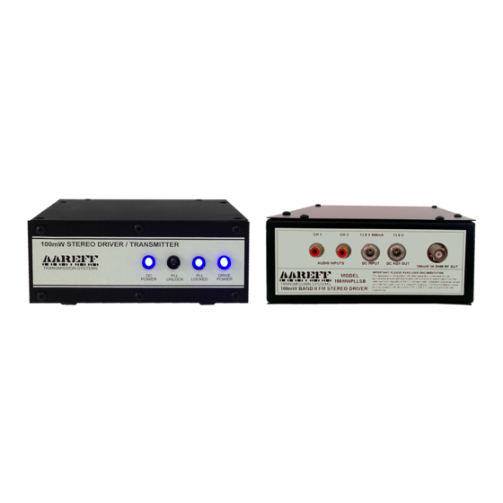
2. SPECIFICATIONS 2.1 FRONT LABEL Transmitter model Manufacturer DC power indicator PLL unlocked indicator PLL locked indicator RF power indicator... -
Page 7: Rear Label
2.2 REAR LABEL Audio Inputs DC Power Input Auxiliary DC Output 100mW 50 ohm RF Output Manufacturer Model User Warning... -
Page 8: Design
2.3 DESIGN The design utilizes a low power oscillator VHF amplified to 100mW of power and phase-locked with a chain to a reference divider quartz oscillator. The 100mW signal is then applied to a 12 pole low pass filter that produces RF final RF output. All this is housed in an metal case fully screened to protect the user from direct contact with RF voltages and to prevent unwanted emissions, local interference and provide to the unit with sufficient RF immunity for the proper... -
Page 9: Technical Data
2.5 TECHNICAL DATA Power Input 13.8VDC o 115/230 VAC 50/60 Hz with PSU RF Power Output 100mW +/- 0.5 dB between -20 and +40 RF Output Connector BNC / 50 ohm Spurious Emissions >66dB rtc Harmonic Emissions >66dB rtc Out of Lock RF Muting >66dB rtc Freq Range 100 KHz steps between 87.5 and 108MHz... -
Page 10: Installation
The installation must be by an engineer that has skills and competancy in EMC and radio frequency systems. The final installation should be in accordance with the site engineering document at http://www.aareff.com/ETR132.pdf. 3.1 AUDIO INPUT AUDIO INPUTS accept stereo audio signals of 0 dBu. The RCA / phono connectors are "Hi-Z"... -
Page 11: Dc Input And Dc Auxiliary Output
3.2 DC INPUT AND DC AUXILIARY OUTPUT DC input and DC auxiliary output are simply interconnected inside the unit. The purpose of this is to enable other equipment to be connected in a DC "daisy chain" and share the same power supply. The DC connectors have a current rating of 5000 mA, therefore if the external power supply can deliver 5000 mA and transmitter consumes 600 mA, this leaves 4400 mA of power available for other... -
Page 12: 100Mw 50 Ohm Rf Output
3.3 100MW 50 OHM RF OUTPUT This is the RF output and produces 100mW of power into a 50 ohm resistive load. This is used to drive a dummy load or antenna or other system that is designed with a 50 ohm input. This output should always be terminated with 50 ohm when the transmitter is powered. -
Page 13: Bottom Panel Controls
3.4 BOTTOM PANEL CONTROLS... -
Page 14: Operation
4. OPERATION 4.1 SETTING RF OUTPUT POWER Locate VR2 RF PWR ADJ shown on the bottom panel photograph of the transmitter. For 100mW (maximum output) turn VR2 RF PWR ADJ fully anti-clockwise (min att). For virtually zero power output (about 1mW) turn VR1 fully clockwise (max att). No other adjustments are necessary. -
Page 15: Adjusting Deviation
4.3 ADJUSTING DEVIATION Adjust VR1 as shown on the bottom panel photograph, this will adjust the complete multiplex signal including the stereo pilot tone. This method should be used to adjust the deviation following a frequency change or a change in an external stereo or RDS generator or audio limiter. -
Page 16: Frequency Lock Codes
5. FREQUENCY LOCK CODES PLL DIL SWITCHES (S2 AND S1) 87.5 OFF OFF 87.6 OFF OFF OFF OFF 87.7 OFF OFF OFF OFF 87.8 OFF OFF OFF OFF 87.9 OFF OFF OFF OFF OFF 88.0 OFF OFF OFF OFF OFF OFF 88.1 OFF OFF OFF OFF... - Page 17 89.7 OFF OFF OFF 89.8 OFF OFF OFF 89.9 OFF OFF OFF 90.0 OFF OFF OFF OFF OFF 90.1 OFF OFF OFF 90.2 OFF OFF OFF 90.3 OFF OFF OFF OFF OFF 90.4 OFF OFF OFF OFF OFF OFF 90.5 OFF OFF OFF 90.6 OFF OFF OFF...
- Page 18 92.4 OFF OFF OFF OFF OFF OFF OFF 92.5 OFF OFF OFF OFF OFF OFF 92.6 OFF OFF OFF OFF OFF OFF 92.7 OFF OFF OFF OFF OFF OFF OFF 92.8 OFF OFF OFF OFF OFF OFF OFF OFF 92.9 OFF OFF OFF 93.0 OFF OFF OFF...
- Page 19 95.1 OFF OFF OFF OFF OFF OFF OFF 95.2 OFF OFF OFF OFF OFF OFF OFF OFF 95.3 OFF OFF OFF OFF OFF OFF 95.4 OFF OFF OFF OFF OFF OFF 95.5 OFF OFF OFF OFF OFF OFF 95.6 OFF OFF OFF OFF OFF OFF OFF OFF 95.7...
- Page 20 97.8 OFF OFF OFF OFF 97.9 OFF OFF OFF OFF 98.0 OFF OFF OFF OFF OFF OFF 98.1 OFF OFF OFF OFF 98.2 OFF OFF OFF OFF 98.3 OFF OFF OFF OFF OFF OFF 98.4 OFF OFF OFF OFF OFF OFF OFF 98.5 OFF OFF OFF OFF OFF OFF...
- Page 21 100.5 ON OFF OFF OFF OFF OFF OFF 100.6 ON OFF OFF OFF OFF OFF OFF 100.7 ON OFF OFF OFF OFF OFF OFF OFF 100.8 ON OFF OFF OFF OFF OFF OFF OFF OFF 100.9 ON OFF OFF OFF OFF OFF OFF 101.0 ON OFF OFF OFF OFF...
- Page 22 103.2 ON OFF OFF OFF OFF 103.3 ON OFF 103.4 ON OFF 103.5 ON OFF 103.6 ON OFF OFF OFF 103.7 ON OFF OFF OFF 103.8 ON OFF OFF OFF 103.9 ON OFF OFF OFF OFF 104.0 ON OFF OFF OFF OFF OFF 104.1 ON OFF 104.2 ON OFF 104.3 ON OFF...
- Page 23 105.9 ON OFF 106.0 ON OFF OFF OFF 106.1 ON OFF 106.2 ON OFF 106.3 ON OFF OFF OFF 106.4 ON OFF OFF OFF OFF 106.5 ON OFF 106.6 ON OFF 106.7 ON OFF 106.8 ON OFF OFF OFF 106.9 ON OFF OFF OFF 107.0 ON OFF OFF OFF...
-
Page 24: Declartion Of Conformity
AVDA ANDALUCIA 1, LA ALFOQUIA-ZURGENA 04661, ALMERIA, ESPANA. Declaramos bajo nuestra responsabilidad la Conformidad del producto: AAREFF 100mW BAND II MPX DRIVER EXCITER (100MWPLLB) al que se refiere esta declaración, con las normas u otros documentos normativos ETS 300 384/A1 ed.1 (1997-02) Sistemas de Radiodifusión. - Page 25 Aareff Transmission Systems SL o por otras partes que han licenciado su material a Aareff Transmission Systems SL. Este documento en parte o en su conjunto no puede ser copiado, reproducido, republicado, cargado, publicado o distribuido en cualquier forma, incluyendo correo electrónico, FTP o...
Need help?
Do you have a question about the 100MWPLLSB and is the answer not in the manual?
Questions and answers