
Summary of Contents for KSB SMARTRONIC MA R1310
- Page 1 SMARTRONIC MA User instructions 42813892 Ref.8520.8041/8-EN SMARTRONIC MA R1310 positioner...
- Page 2 SMARTRONIC MA...
- Page 3 SMARTRONIC MA Item Designation Materials Cover Polycarbonate SM60/0 160.1 Distributor cover Polycarbonate SM60/0 163.1 Bonnet Polycarbonate SM60/0 163.2 Bonnet Polycarbonate 165.1 Bonnet 191.2 Support Laiton nickelée 191.3 Spacer 198.1 Connection plate 210.1 Shaft Polycarbonate SM60/0 314.1 Friction washer Inox 304L 400.1 Gasket Neoprene...
- Page 4 SMARTRONIC MA Installation and commissioning of the electropneumatic actuators must be carried out in accordance with instrumentation professional standards, and in particular: Piping: When commissioning a new or modified installation, the piping must be blown through before connecting the actuator in order to clear the circuit Warnings of any impurities, which cannot be avoided during construction (iron filings, scale, Teflon, welding flux, etc.).
-
Page 5: Table Of Contents
SMARTRONIC MA Contents Page I - Introduction I- 1 General I- 2 Operating principle I- 3 Technical characteristics II - Assembly on pneumatic actuator II - 1 ACTAIR 3 to 200, ACTAIR NG 2 to 160, DYNACTAIR 1.5 to 100 and DYNACTAIR NG 1 to 80 9 II - 2 ACTAIR NG 240 to 700 et DYNACTAIR NG 120 to 350 II - 2 ACTAIR 400 to 1600 and DYNACTAIR 200 to 800 and other ¼... - Page 6 VIII - 2 Global organisation VIII - 3 Detail of the file tree structure content VIII - 3 - 1 ”KSB Hart Positioner” directory VIII - 3 - 2 ”Operation” directory VIII - 3 - 2 - 1 ”System” directory VIII - 3 - 2 - 2 ”Endstop sensors”...
-
Page 7: I - Introduction
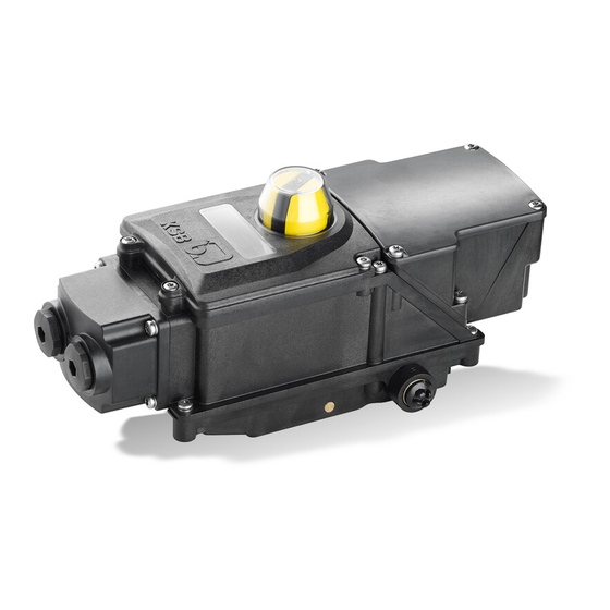
SMARTRONIC MA I - Introduction I - - 1 General This manual describes the SMARTRONIC MA positioner. This device is designed to control the quarter- turn actuators of the ACTAIR and DYNACTAIR range by direct surface mounting on the standardized VDI/VDE 3845 interface. It provides both the direct pneumatic and mechanical link with the actuator chambers. -
Page 8: Technical Characteristics
SMARTRONIC MA I - 3 Technical Characteristics Electric connections Accepts flexible conductors with end connector and with insulating entry cone of cross- section 0.25 mm to 0,5 mm Weight 1,70 Kg Environment Standard protection class IP 67 according to EN 60529 Electromagnetic Compatibility Complies with European directive EMC 2004/108/EC according to standards NF EN 61000- 6- 2 et NF EN 61000- 6- 4... -
Page 9: Assembly On Pneumatic Actuator
SMARTRONIC MA II - Assembly on pneumatic actuator II - 1 ACTAIR 3 to 200, ACTAIR NG 2 to 160, DYNACTAIR 1.5 to 100 et DYNACTAIR NG 1 to 80 Adaptation kit for ACTAIR NG and DYNACTAIR NG A- Check that the actuator has both plugs (item 1) on the external supply holes. B- Remove the two screws with seals (item 2) (TORX T20 screwdriver). -
Page 10: Actair Ng 240 To 700 Et Dynactair Ng 120 To 350
SMARTRONIC MA II – 2 ACTAIR NG 240 à 700 et DYNACTAIR NG 120 à 350 Adaptation kit for ACTAIR NG and DYNACTAIR NG A- Position the adaptations elements for ACTAIR NG and DYNACTAIR NG B- Fix the adapter kit plate to the actuator interface with 4 M5 screws C- Separate the unit (item 9) from the base (item 4) by unscrewing the 6 screws (item 10) (TORX T20 screwdriver). -
Page 11: Actair 400 To 1600 And Dynactair 200 To 800 And Other ¼ Turn Actuators
SMARTRONIC MA II - 3 ACTAIR 400 to 1600 and DYNACTAIR 200 to 800 and other ¼ turn actuators These instructions only relate to pneumatic ¼ turn actuators whose flange complies with VDI/VDE 3845 with the following dimensions: A = 80 mm; B = 20 mm (actuator shaft height). For the other VDI/VDE dimensions, please contact us. -
Page 12: Linear Actuators
SMARTRONIC MA II - 4 Linear actuators 8 - 9 1’ 13 - 14 28 - 27 15 – 15’ 16 - 17 22 - 23... - Page 13 SMARTRONIC MA These instructions only relate to linear pneumatic actuators which comply with VDI/VDE 3847 with rod-shaped pillars: For the other actuator types, please contact us. A – Check that the base (item 1) supplied with the unit is intended for this type of actuator. It must have two ¼”...
-
Page 14: Assembling The Smartronic Ma/Actuator Assembly On The Valve
SMARTRONIC MA III - Assembling the SMARTRONIC MA/Actuator assembly on the valve Use of an angle sensor with no mechanical stops makes it easier to assemble the positioner on the valve. It is essential to perform a complete opening/closing cycle up to the actuator mechanical stops so that the angle sensor takes up the correct position. -
Page 15: Mechanical Adjustment Of The Operating Time
SMARTRONIC MA IV - 2 Mechanical adjustment of the operating time Mechanical adjustment of the operating time is carried out in the factory to obtain the best accuracy/speed compromise for the positioner. Mechanical modification of the operating times could prevent the positioner from operating correctly. After making these modifications, it is essential to perform autocalibration. -
Page 16: Safety Position On Loss Of Current
SMARTRONIC MA Distributor - Solenoid valve unit Adjustment screw R2 Adjustment screw R1 Action direction of brakes R1 and R2 ACTAIR 3 to 1600 Stop on closing (standard version) Closing time Opening time Stop on opening (upon request) Opening time Closing time Safety position on loss of DYNACTAIR 1.5 to 800... - Page 17 SMARTRONIC MA See chapter on spare parts kit to change the safety position Plate A Plate B The 2 plate types Location of the plate affecting the safety position Depending on the plate used (A or B) and depending on the actuator size, we obtain different safety positions on loss of current.
-
Page 18: Electric Connections
SMARTRONIC MA V - Electric connections V - 1 Connection housing To access the electric connection terminal block, unscrew the 4 TORX s crews (T 20) in the connection housing Tightening torque: 2 Nm Seals Connection housing V - 2 Connections to the 4- 20 mA current loop Use a screened cable for the 4- 20 mA signal with the screening connected to the current generator earth, since the Smartronic MA box has no earthing. -
Page 19: End Stop Connection
SMARTRONIC MA V - 3 End stop connection SMARTRONIC MA R1310 terminal block Proximity detectors Mechanical microswitches Technical characteristics of mechanical microswitches (Crouzet ref.: 83181) - Box: thermoplastic polyester loaded with glass fibre, Material: Button: polyamide UL 94 V0 loaded with glass fibre, - Contact: nickel- plated silver. -
Page 20: Feed- Back Position (Option)
SMARTRONIC MA V - 4 Feed - back position (Option) The SMARTRONIC MA positioner may be fitted with an optional position recopy board delivering a 4- 20 mA output signal. Max. load 1000 Ohms Power supply 15 to 24 VDC Technical Characteristics Power Supply 15 to 24 VDC... -
Page 21: Local User Interface
SMARTRONIC MA VI - Local user interface The local user interface consists of four buttons <+>, <->, <OK>, <ESC> and an LCD screen segmented as follows: Screen contrast adjustment VI - 1 Cover To access the local user interface or the cam adjustment, unscrew the 4 TORX screws (T 20) in the cover. -
Page 22: Main Screen
SMARTRONIC MA VI - 2 Main screen: Operating mode AUTO : Automatic positioning (4- 20 mA setpoint) MANU : Manual positioning (local interface) HART : Positioning by HART (HART setpoint) NO CALIB : Device not calibrated AUTO Parameter value POS 50.0% Parameter: POS : Valve position SSR : value of the position sensor (if NO CALIB) -
Page 23: Submenu Screen
SMARTRONIC MA VI - 3 Submenu screen To access the submenus: - Press buttons <OK> and <ESC> simultaneously for 5 seconds. - Navigate with the <+> and <-> buttons. - Validate with <OK>. - Cancel with <ESC>. Indicates the presence of a submenu Path Submenu title... - Page 24 SMARTRONIC MA General structure of the local user interface...
-
Page 25: Implementing The Smartronic Ma
SMARTRONIC MA VII - Implementation of the SMARTRONIC MA Valve position visual indicator LCD screen Screen contrast adjustment Navigation buttons potentiometer Electric connection terminal block Please note: To achieve a stable control process and prevent premature wear of the valve/actuator/positioner assembly, we strongly recommend defining a control dead band at the PID regulator in order to limit the setpoint variations transmitted to the positioner. -
Page 26: Starting Auto-Calibration
SMARTRONIC MA VII - 2 - 2 Starting auto-calibration Autocalibration must be carried out in the following cases: - First time use of the positioner - Modification of the actuator mechanical stops - Modification of the mechanical adjustment of the operating time - Modification of an external parameter that could affect the device positioning performance The autocalibration procedure optimises the positioner adjustment by calculating the gains, sensitivity in dead band for the opening and closing operations. -
Page 27: - 2 Manual Mode
SMARTRONIC MA VII - 3 - 2 Manual mode >main menu >3.settings >3>1.mode >3>1>2.manu >3>1>2.manu <OK> <OK> <OK> <OK> <+> or <-> 3.SETTINGS > 1.MODE > 2.MANU VALID ? <ESC> <ESC> <ESC> <ESC> <OK> or <ESC> pos : 50.0 % The operator can: - Position the valve manually, - The angle sensor stroke automatically by moving to the actuator mechanical stops (see §VII- 2-1). -
Page 28: Adjusting The End Stop Detectors
SMARTRONIC MA VII - 4 Adjusting the end stop detectors The cams are preset in the factory. Their positions can be adjusted if the actuator mechanical stops are modified. Cover To access the cam adjustment, unscrew the Visual index 4 TORX screws (T 20) in the cover. Tightening torque: 2 Nm - Make the electric connections of the end stops (see §V - 3) - Bring the positioner to an extreme position (O or C) in manual mode (see §VII - 3 - 2) -
Page 29: Function Of The Smartronic Ma Positioner
SMARTRONIC MA VII - 5 Other function of the SMARTRONIC MA positioner VII - 5 - 1 Manual calibration Once the first autocalibration has been carried out, the operator can access the gain, dead band (DB) and positioning stroke values (O/C POSITION see § VII - 5 - 1 - 1). >3>2>1.auto CALIB DONE <OK>... -
Page 30: - 1 - 2 Positioning Dead Band
SMARTRONIC MA VII - 5 - 1 - 2 Positioning dead band This setting is used to adjust the positioner dead band. Although it is calculated automatically during autocalibration, this parameter can be adjusted manually. <ESC> <OK> >main menu >3.settings >3>2.calib >3>2>manu >3>2>2>2.db... -
Page 31: - 2 Adjusting The Setpoint According To The 4- 20 Ma Signal
SMARTRONIC MA VII - 5 - 2 Adjusting the setpoint according to the 4- 20 mA signal The operator can define two setpoint current values I1 (mA) and I2 (mA) which are associated with two position setpoints, respectively P1 and P2. The positioner will move linearly between these two points. -
Page 32: - 4 Safety Position By Lack Of Power
SMARTRONIC MA VII - 5 - 4 Safety position by lack of power Warning : This parameter is factory set and must correspond to the equipment configuration of the non- functional product. The values "1 - UNDEF" "3-CLOSE" and "OPEN-4" are interchangeable from a functional point of view. They are used for the boxes with the following references: - R131 * / **** 1 *** B * B2 * 0600 - R131 * / **** 1 *** B * A2 * 0600... -
Page 33: - 7 Configuring The Main Screen Display
SMARTRONIC MA VII - 5 - 7 Displaying positioning data The SMARTRONIC MA allows read only access to the values required for its positioning, via the ”OPERATION” menu. - ”In CURRENT” indicates in mA the setpoint current in the 4- 20mA input loop - ”SETPOINT”... -
Page 34: Hart Parameters
SMARTRONIC MA VIII - HART parameters VIII - 1 Installing the Device Description (DD) file VIII - 1 - 1 SDC625 Add the content of the Device description file in directory: C:\HCF\DDL\Library VIII - 1 - 2 Pocket 375 Add the content of the Device description file in directory: C:\Program Files\375 Easy Upgrade Utility\PC Database\DD\HART Then add this DD to the Pocket 375 database using the program: 375 Easy Upgrade Programming Utility*... -
Page 35: Detail Of The File Tree Structure Content
- The valve - The typical HART data VIII - 3 Details of the file tree structure content VIII - 3 - 1 ”KSB Hart Positioner” directory Operation (cf. VIII - 3 - 2) Diagnosis (cf. VIII - 3 - 3) Settings (cf. -
Page 36: - 2 - 3 "Hart Setpoint" Directory
SMARTRONIC MA VIII - 3 - 2 - 3 ”HART setpoint” directory - - HART position Setpoint: Position setpoint as a % if product is operating in HART mode (read/write) VIII - 3 - 3 ”Diagnosis” directory VIII - 3 - 3 - 1 ”Number of operations” directory - - Number of operation: Number of opening/closing cycles (read only, but can be reset) VIII - 3 - 3 - 2 ”Run time”... -
Page 37: - 4 - 2 "O/C Fct Point" Directory
SMARTRONIC MA Regulator gain (read/write) -- Opening gain: (see §VII - 5 - 1 - 3) -- Closing gain: (see §VII - 5 - 1 - 3) Regulator dead band (read/write) -- Opening dead band as a % (see §VII - 5 - 1 - 2) -- Closing dead band as a % (see §VII - 5 - 1 - 2) VIII - 3 - 4 - 2 ”O/C fct point”... -
Page 38: - 5 "Info" Directory
VIII - 3 - 5 ”Info” directory VIII - 3 - 5 - 1 ”Device” directory - - Manufacturer: Name of positioner manufacturer (KSB) (read only) - - Model: Product name (Smartronic MA) (read only) - - Tag: Free text (max. 8 characters). It is recommended to use a unique name for each device in the HART network. -
Page 39: - 5 - 4 "Valve" Directory
SMARTRONIC MA VIII - 3 - 5 - 4 ”Valve” directory - - Vendor: Name of valve manufacturer (read/write) - - Type: Valve type (read/write) - - Size: Valve size (read/write) - - Write valve info: (recommended) Function used to complete all the information fields concerning the valve and save them (write only) VIII - 3 - 5 - 5 ”HART”... -
Page 40: Operating Faults - Causes And Solutions
SMARTRONIC MA IX - Operating faults - Causes and solutions Operating faults Causes Corrections On power up, the display does not come on - Check the current loop: - Set the installation in conformity after 3 seconds incorrect wiring and loop current I < 3.8 mA - Adjust the contrast - Turn the blue potentiometer - Electronic board out of service... -
Page 41: Codes
SMARTRONIC MA X - Codifications Codification Designation R001310 / ..1 . . . B . . 2 . 0 6 0 0 SMARTRONIC MA Detection R- - -- - - - - -- - - / 1 0 0 0 1 . -
Page 42: Spare Parts Kit
SMARTRONIC MA Codification Designation Smartronic function R- - -- - - - - -- - - / ..1 . . . B . . 2 . 0 6 0 0 Intelligent positioner Field bus R- - -- - - - - -- - - / . - Page 43 SMARTRONIC MA...
- Page 44 SMARTRONIC MA KSB S.A.S 4, allée des Barbanniers 92635 Gennevilliers Cedex (France) Tél. : +33 (1) 41 47 75 00 www.ksb.com...
Need help?
Do you have a question about the SMARTRONIC MA R1310 and is the answer not in the manual?
Questions and answers