Table of Contents
Advertisement
Quick Links
TEAM DIGITAL
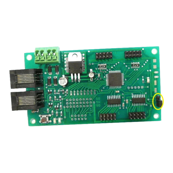
SC82
Servo Controller
Version C proto hardware shown.
Production hardware has all servo
connectors in one line.
> DCC compatible accessory decoder
> Control 8 servos motors
> Output status LEDs
> 8 inputs for turnout control
> 16 inputs for semaphore signaling
> 8 configurable routes
> "Smart" Programming
> DCC gateway to serial bus
> LocoNet
®
compatible serial bus
Description
The SC82 is a DCC compatible accessory decoder.
It can control up to 8 servo motors that can be used
for switches (turnouts) or semaphores. It can drive
LEDs for turnout state. The inputs can be used for
push buttons to control switches or block detectors to
control semaphores. It has route capability for
multiple turnout control.
The SC82 can be used as a stand-a-lone controller or
communicate with other devices that have a
compatible serial bus.
Using the serial bus, one SC82 could control another.
Push buttons connected to the inputs of one SC82
can control servo connected to another SC82. A route
defined in SC82 could include servos controlled by
another SC82. The serial bus can help in reducing
and simplify the wiring.
The SC82 works out of the box with no
programming. If you you need to change servo
position or addresses its as easy as issuing switch
commands or controlling loco speed. If custom
operation is required, CVs can by programming by
the DCC system.
09.01.15
LocoNet is a registered
trademark of Digitrax Inc
Inputs for:
Push button switch control
Semaphore signaling
Inputs only for:
Semaphore signaling
Track Power
or DC
9.5 -16 V
1
Improving the world of DCC
1
1
Inputs
Outputs
1 to 8
1 to 8
SC82
1
1
Inputs
Outputs
9 to 16
9 to 16
LED3
SG 5V GD
SG 5V GD
8
Power
5
LED1
LED2
Serial Bus
6 pin RJ12
Serial bus used to communicate:
Switch state/control
TEAM DIGITAL, LLC
3111 Timber Valley Dr
Kokomo IN 46902
www.teamdigital1.com
Outputs for:
LED indicators
Outputs for:
4
Servos
1
Smart Button
Advertisement
Table of Contents

Subscribe to Our Youtube Channel
Summary of Contents for Team Digital SC82
- Page 1 LED indicators multiple turnout control. Inputs only for: Inputs Outputs Semaphore signaling The SC82 can be used as a stand-a-lone controller or 9 to 16 9 to 16 communicate with other devices that have a LED3 compatible serial bus. SG 5V GD...
-
Page 2: Table Of Contents
2.3 Servo Move Direction 2.4 Switch Position Indication 3 “Smart” Programming 4 Configuration Variables (CVs) 4.01 Changing servo position 4.02 Reset the SC82 to factory defaults 4.1 Servo Output Address 4.2 Servo Position and Range 4.3 Servo Move Speed 4.4 Decoder Configuration 4.5 Status Report... -
Page 3: Operation
2 Getting Started The SC82 comes from the factory ready to use with addresses of 1 to 8. Once you plug in the servos cables, centered the servos (section 2.2) and mounted them you are ready to use the SC82. If you want to change some of the addresses or adjust servo movement see the “Smart”... -
Page 4: "Smart" Programming
Part 1: To change addresses and mode, press the “Smart” program button and hold it down for approximately one second until LED1 (red) starts to flash. Then release it. The SC82 is now ready to have the addresses changed. You can set eight sequential addresses in one (first) step or continue and set each of the individual servo addresses (non-sequential). - Page 5 Continue to hold it down until LED2 (green) turns on. Then release it. LED1 will be flashing and LED2 will be on. The SC82 is now ready to have the servo movement changed. You need to be able to see the servo arm, switch or semaphore to make adjustments.
-
Page 6: Configuration Variables (Cvs)
When the green LED turns on release the button then wait until the red LED turns off. The SC82 is now in ops mode until power is turned off. The default ops address is one (1). This is a loco address, so be careful when using this feature. -
Page 7: Reset The Sc82 To Factory Defaults
4.02 Reset the SC82 to factory defaults To “reset” the SC82 to factory defaults, turn power on and wait until LED 1 turns off. Then press the “Smart” button and continue to hold the button down (at least 16 seconds) until both LED 1 & 2 are alternately flashing. Alternately, programming CV7 with 170 will “reset”... -
Page 8: Status Report
(DCC commands) This table will help you determine how to configure the SC82. If there are more than one SC82 or other Gateway capable devices, only one should have the gateway enabled. In a Digitrax system DO NOT connect the SC82 to the throttle Loconet if the gateway, DCC control and serial bus are enabled. -
Page 9: Route Execute Address
A route is executed when a turnout (switch) command from any source including those from the SC82, throttles or computers matches the top address and switch state for that route. To increase a route to greater than than eight turnouts, give more than one top address the same address. -
Page 10: Route Address Send Delay
This CV sets the operations mode program address. This address is used ONLY for programming and has NOTHING to do with normal operation. This allows programming the SC82 just like you would a loco in ops mode. This is a loco 2 digit address and therefore must be unique among locomotive addresses. -
Page 11: Connections
5.1 Power The SC82 is powered by using the two terminal connector labeled Power. See diagram on front page. Power can be from the track (accessory decoder operation) or a filtered DC voltage (9.5 to 12 VDC) power supply. For a DC supply do not use old analog 'Power Packs'. -
Page 12: Applications
6 Applications 6.1 Wiring Examples These diagrams show wiring for push buttons and LEDs that can be used with the SC82 for switch control. Product Output# Pin# Product Input# Pin# GND - 5 1 2 3 4 5 6 7 8 9 10... -
Page 13: Routes
Simple ABS semaphore signaling of up to 8 semaphores can be implemented with just block and optionally turnout state devices connected to the SC82 inputs. No programming is required except a couple of Smart programming steps. Use Smart programming Part 1 for 8 sequential addresses for 3 positions (mode 2). - Page 14 2 is unoccupied, servo 1 is in the red position and servo 2 is in the yellow position. If both blocks are occupied then both servo are in the red position. The TSAs provide for easy connection to the SC82 inputs.
-
Page 15: Summary Of Configuration Variables
7 Summary of Configuration Variables Function/Default Value Function/Default Value Function/Default Value Ops Mode Loco Address Servo 3 Address Route 4 Top Address Adder reserved Servo 3 Address Adder Route 5 Top Address reserved Servo 4 Address Route 5 Top Address Adder reserved Servo 4 Address Adder Route 6 Top Address... - Page 16 Function/Default Value Function/Default Value Function/Default Value Route 4 Cell 2 Address Route 7 Cell 8 Address Route 4 Cell 2 Address Adder Route 7 Cell 8 Address Adder Route 4 Cell 3 Address Route 8 Cell 1 Address Route 4 Cell 3 Address Adder Route 8 Cell 1 Address Adder Route 4 Cell 4 Address Route 8 Cell 2 Address...
Need help?
Do you have a question about the SC82 and is the answer not in the manual?
Questions and answers