Table of Contents
Advertisement
Quick Links
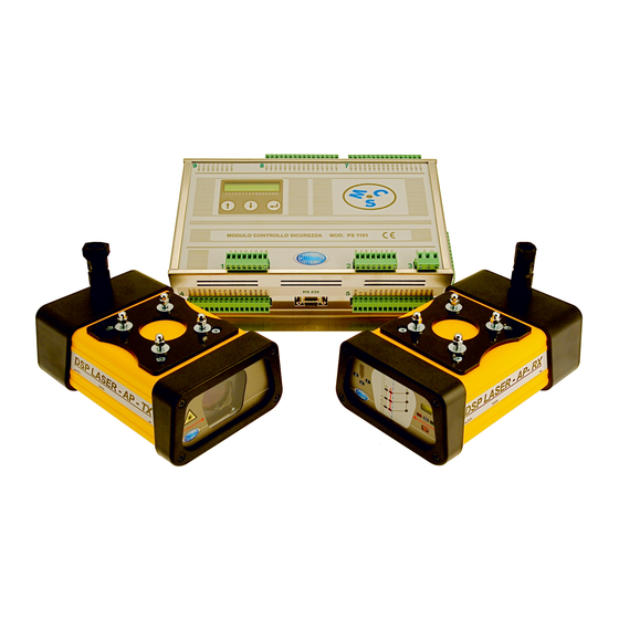
MCS and DSP LASER AP
INSTRUCTION MANUAL
SAFETY DEVICE FOR PRESS BRAKES
WITH
VISIBLE LASER EMISSION
Revision 1.1 of 20.11.2012
NUOVA ELETTRONICA s.n.c. di Pasqui F. & C.
Via Parri ZI Moiano - 06062 Città Della Pieve - PG - ITALIA - UE
Tel. : +39 (0)578 298066 Fax: +39 (0)578 297007
web: www.nuova-elettronica.com e-mail:
info@nuova-elettronica.com
DLAM01EN
Rev. 1.1 – Ed. 20/11/2012
Advertisement
Table of Contents

Related Manuals for NUOVA ELETTRONICA MCS

Summary of Contents for NUOVA ELETTRONICA MCS
- Page 1 WITH VISIBLE LASER EMISSION Revision 1.1 of 20.11.2012 NUOVA ELETTRONICA s.n.c. di Pasqui F. & C. Via Parri ZI Moiano - 06062 Città Della Pieve - PG - ITALIA - UE Tel. : +39 (0)578 298066 Fax: +39 (0)578 297007 web: www.nuova-elettronica.com e-mail:...
- Page 3 Status of manual Manual code: DLAM01EN Revision: Issue: 20/11/2012 Chronology of document revisions Date Revision Summary of changes 15/09/2012 Draft 20/11/2012 First issue Copyright information Possible information about copyright...
-
Page 5: Table Of Contents
Preparation ........................... 30 10.3.2.2. Installation ............................ 33 10.4. Electric connection ...................... 34 10.4.1. List of signals managed by MCS ................. 34 10.4.2. MCS electric connection ..................... 40 10.4.2.1. Machine power supply connection ....................40 10.4.2.2. Foot Pedal Controls with “antipanic” and Emergency chain ............41... - Page 6 10.4.4. Electric connection of other front protections ...............58 Commissioning ......................59 11.1. Power supply and first functional verification ...............59 11.2. List, description and programming of MCS parameters ..........59 11.2.1. List of parameters and description ................60 11.3. System Test ........................67 11.4. First installation of TX and RX ..................71 11.5.
-
Page 7: Foreword
It defines the purpose which the equipment has been created for and contains all the information necessary to ensure a correct and safe use. Nuova Elettronica, in pursuing a policy of continue development and update of the product together with the evolution of the state-of-art of the laser safety devices for press brakes, can carry out changes without any notice. -
Page 8: Symbols Used In The Manual
DSP LASER AP with MCS Symbols used in the manual The important information has been highlighted and accompanied by the word: Lack of reading this information can cause serious dangers for the operator Warning: The information signals a risk which had been impossible to eliminate... -
Page 9: Warranty
Technical and Repair Service, as the replies to the request of specific information or explanations, are provided directly by the equipment manufacturer: NUOVA ELETTRONICA s.n.c. of Pasqui F. & C. Via Parri ZI Moiano - 06062 Città Della Pieve - PG - ITALIA - UE Tel. -
Page 10: Safety Precautions
• Check the operating voltage of the device before use. The operating voltage (24Vcc ± 10%) is indicated on the plate located on MCS module. The device is not disconnected from mains until MCS module is physically connected to the electric panel, even if the device seems “off”. -
Page 11: Legend
(Fast Speed) to safety or work speed, lower than or equal to 10 mm/sec (Low Speed) PROGRAMMING MCS parameters which can be changed, through proper procedure, to PARAMETERS configure functions and outputs of MCS Sliding layer of the bend line during the punch movement... - Page 12 FEEDBACK TIME inside the detection area of DSP LASER AP device and the moment when MCS outputs switch to OFF state Name of the transmitter part of DSP LASER AP. It generates and emits the laser beam and the system synchronism...
-
Page 13: Planning Safety Measures
CEI EN 61496-1:2005 and CEI CLC/TS 61496-2:2007. It can be classified as ESPE of type 4 MCS device has been, moreover, designed respecting even the indications specified by the standard EN 12622:2009 The laser contained in DSP LASER is classified as CLASS 1M, according to standard CEI EN 60825-1:2009. -
Page 14: Overview
Types of front protections controlled by MCS As you can see in Figure 1, MCS controls the photoelectric device DSP LASER AP as main component for the protection against the access to the front part of the bending machine. - Page 15 DSP LASER AP with MCS Section for the monitoring of speed/position/direction Figure 2 Figure 2 shows a scheme of the section which allows connecting in parallel to channels A and B of the two, usually linear, encoders present on the synchronized press. They measure the stroke of the hydraulic jacks responsible of the movement and the operation of the moveable table.
- Page 16 LEFT SIDE GUARD REAR GUARD TOLL AUTOMATIC CLAMPING CUTTING SYSTEM for ROBOT HEMMING OPENING CONTROL DSP LASER AP OPERATING MODES Figure 3 Figure 3 represents the components which can be connected to MCS inputs to be controlled and monitored. DLAM01EN...
- Page 17 DSP LASER AP with MCS Safety outputs and monitor inputs Figure 4 represents the MCS safety outputs which are realized at solid state, have high current in output and are synchronized with the MCS inputs available for the possible monitors of the devices they control.
- Page 18 Keys for the selection of the operation options. DISPLAY KEYS Figure 6 The second interface is realized by the CNC display. The data and the messages to display are processed by CNC depending on the signals coming from MCS through the serial port. DLAM01EN...
-
Page 19: Dsp Laser Ap
DSP LASER AP with MCS 8.1.2. DSP LASER AP The safety device DSP LASER AP is a visible laser emission barrier which, realized and placed as described in Standard EN12622, protects the operator of the press brake against the danger to be squashed between the upper tool and the lower tool during the closing of the press in high speed. - Page 20 The detection of the sheet thickness is executed by the central sensor of the Area A. Note. If the machine Stop Distance, measured by MCS during the test, is less than 6mm, the Area A is automatically disabled by DSP LASER AP during the normal operation.
- Page 21 MCS ensures the STOP of what monitored. The typical use of the system foresees the mechanical installation of the transmitter and of the receiver on the upper table and the installation of MCS module inside the electric panel of the press brake.
-
Page 22: Operating Cycle Of A Press Brake
Information: The activation of the safety outputs of MCS device, dedicated to the control of the movement of the moveable crossbeam, can be configured according to the following states of the working cycle of the press brake: •... -
Page 23: Signals And Plate Data
9.1.1. MCS module FRONT PANEL MCS front panel (Figure 9) contains the LEDs indicating the state 1 (led on) or 0 (led off) of the safety inputs, the LEDs indicating the state ON (led on) or OFF (led off) of the safety... - Page 24 Moreover, it displays errors, alarms and other parameters useful to the user. The part of MCS front panel which regards the display and the keys is reported in Figure 10. Figure 10 DLAM01EN...
- Page 25 Figure 11 Screen 1: Line 1: Product name: MCS and factory model name: PSA 1B01C33 Line2: SA value (measured Stop Distance) expressed in mm (or xx if the SA test has not been executed yet) and result of AV (High Speed) measurement expressed in mm/s (or maximum value reachable from AV=330 mm/s if the SA test has not been executed yet).
- Page 26 DSP LASER AP with MCS Pressing ARROW UP key, you access to the fourth screen (Figure 14). Figure 14 Screen 4: Line 1: Position (in mm) of axis Y1 with respect to sheet edge, with resolution of tenth of Line 2: Position (in mm) of axis Y2 with respect to sheet edge, with resolution of tenth of Pressing ARROW UP key, you access to the fifth screen (Figure 15).
- Page 27 RIF 0V: One of the connections where the reference 0V of MCS power supply is available. 0Vcc, 24Vcc: One of the two connections to MCS power supply by means of terminals 0Vcc and 24Vcc (see par. 10.4.2.1). OUT V: Output which communicates, rapidly, to CNC that the lowest central sensor (Area A) of DSP LASER AP has intercepted the sheet.
- Page 28 ON(24Vcc)=1 or OFF(0Vcc)=0 is shown on the display (Figure 13). RIGHT PANEL On the right face of MCS module (Figure 18) you can see the type and the numbering of the inputs and the outputs connected to the relevant connector and the numbering assigned to the connector.
- Page 29 DSP LASER AP with MCS LEDs installed on machine board and controlled by MCS The LEDs installed on machine board by the Manufacturer must match the requirements regarding the colour and the position on the machine as required by the current laws.
-
Page 30: Dsp Laser Ap
DSP LASER AP with MCS 9.1.2. DSP LASER AP RECEIVER RX front panel (Figure 19) contains the slots for the passage of the light necessary to the receiving elements of the three sensitive areas, the LEDs indicating operation modes and states and references to mechanically place RX with respect to the laser beam already set and, then, to the machine. - Page 31 The GREEN LED OFF indicates that at least one receiver of any active area has been shaded. The LED ON indicates that all the active receivers are lighted. The WHITE LED OFF indicates MCS in active operation. The LED ON indicates MCS in lock state.
-
Page 32: Identification Plates
DSP LASER AP with MCS 9.2. Identification plates 9.2.1. MCS module MCS identification plate (Figure 21) reports the following data: • Name, address and contact references of the device Manufacturer • Logo “Costruito in Italia” • Inputs and outputs, if properly connected, can reach SILCL3 •... -
Page 33: Transmitter
DSP LASER AP with MCS DSP LASER AP-RX side plate (Figure 23) reports the following data: • Device part: DSP LASER AP-RX • Serial number (N.S.) and manufacturing date (DATA) Figure 23 9.2.3. Transmitter DSP LASER AP-TX rear identification plate (Figure 24) reports the following data: •... -
Page 34: System Characteristics And Installation
DSP LASER AP with MCS System Characteristics and Installation MCS with DSP LASER AP is high safety level system. It is however essential that it is correctly installed and used according the following instructions. 10.1. Standard supply MCS with DSP LASER AP consists in the following elements: •... -
Page 35: Preparation
Figure 27 indicates the positions for the drilling of the panel on the four points, marked with the letter “F”, where MCS will be fastened. Then drill the four holes for the fastening and the relevant threads, if no self-threading screws will be used. -
Page 36: Installation
10.3.1.2. Installation Fasten MCS module to the electric panel in stable way by means of four screws of proper size, for example TC M5, with length in function of the shape of the electric panel. - Page 37 DSP LASER AP with MCS Figure 28 indicates the dimensions of TX and RX, which are identical. Figure 28 The moving supports must be firmly fastened to the upper tool-holder table, for example by means of plates provided with extensions for the moving supports of TX and RX (Figure 29).
- Page 38 DSP LASER AP with MCS • The distance between the front part of TX and RX and the basement of the press is greater than or equal to 100 mm, with the purpose to avoid the hand squashing. • The design of the moving support of the device must be such not to create entrapment points during the upward and downward movements of the press.
-
Page 39: Installation
DSP LASER AP with MCS 10.3.2.2. Installation TX and RX containers are provided with four stud bolts (Figure 28) for the fastening to the corresponding moving supports. Fasten, then, TX and RX to the supports by means of these couplings and tighten the supplied 5MA thread nuts. -
Page 40: Electric Connection
Electric connection 10.4.1. List of signals managed by MCS The pins (I/O) on the SAFETY CONTROL MODULE, called MCS, are listed in the following table which describes their function. The safety outputs, from OUTS1 to OUTS8 and the relevant inputs for the possible monitors... - Page 41 DSP LASER AP with MCS Pin name Function Note SAFETY INPUTS enabled by the relevant pulsed outputs INP1 Input for pulsed Output, Antipanic chain A, NC INP2 Input for pulsed Output, Antipanic chain B, NC INP3 Input for pulsed Output, Emergency chain A, NC...
- Page 42 DSP LASER AP with MCS OUTS5 OUT5/EV 5 OUTS6 OUT6/EV 6 OUTS7 OUT7/EV 7 OUTS8 OUT8/EV 8 GENERIC INPUTS 24Vcc 7mA ING1 Upper Tool Holder Command ON/24V ING2 Sheet Edge request button NO ING3 Emergency Reset button NO ING4 Rear Guard Reset button NO...
- Page 43 When the value “ON1” is assigned, these outputs will be active if the machine is not in emergency. This configuration can be used to set other devices in emergency or to signal to other safety devices, as the safety PLC of a Robot, that MCS is in emergency. Information: •...
- Page 44 OUTS5, OUTS6, OUTS7 and OUTS8, you wish to use as safety output controlled by MCS and which not. The selected one will be controlled by MCS and will assume, in the different machine states, the state assigned by the parameters C2, C5, C8 and C11.
- Page 45 “any value”. In this way, the signal OUTG12 will assume the value 24V when MCS will be in a state different from Lock, while it assume the value 0V when MCS will Be in Lock.
-
Page 46: Mcs Electric Connection
The configuration can however be reduced depending on the machine needs. 10.4.2.1. Machine power supply connection Figure 33 illustrates how connect MCS to the 24 Vcc power supply line present in the machine electric panel. The power consumed by MCS is 10W and includes even the power supply of DSP LASER AP. -
Page 47: Foot Pedal Controls With "Antipanic" And Emergency Chain
If the value “2P MS” (2 Pedals Master-Slave) has been assigned to B2, the downstroke request is acquired by MCS when both the pedals are pressed. In this case, however, the Slave (Pedal 2) must be pressed before the Master (Pedal 1), otherwise MCS will signal Error. - Page 48 Information: Should the RS232 connection between CNC and MCS be interrupted or work in wrong way, with selector in position 2 (INS3=0V and INS4=24V), MCS will set to default configuration, where both the foot pedal controls are active: this to ensure the safety of the operator.
- Page 49 (Chap 11.5), the “Sheet Edge Acquisition” function activates. Once this function has been correctly executed (Chap. 11.6), MCS enters in work mode. Now, in order to execute the “Sheet Edge Acquisition” function once more, it is sufficient to press the Sheet Edge request button: the function will activate.
- Page 50 DSP LASER AP with MCS Figure 34 DLAM01EN...
-
Page 51: Rh And Lh Side Guards And Other I/O
This button allows clearing the rear guard alarm, stated that the guard is closed (or the photoelectric barrier is not interrupted). The relevant led ON indicates that the alarm is active and MCS is in Lock state. The led OFF indicates that the alarm is not active. - Page 52 DSP LASER AP with MCS Blinker The blinker indicates if the crossbeam is going down in Low Speed, and then with the front protection (DSP LASER AP) inhibited. • Blinking ON: front protection (DSP LASER AP) inhibited. • OFF: front protection active.
-
Page 53: Emergency Of Auxiliary Devices
This configuration can be used to set other devices in emergency or to communicate to other safety devices, as the safety PLC of a Robot, that MCS is in emergency. In this last case, the outputs can be directly connected to the safety inputs of the device without using the relays. -
Page 54: Automatic Tool Clamping
OFF (0V = clamps closed) to state ON (+24V = grippers open) and, as consequence, the control signals of the relevant pressure switches connected to INS23 and INS24 switch from state ON (+24V = clamps closed) to state OFF (0V = clamps open), MCS enters in state STOP (only the upstroke movement is allowed). -
Page 55: Connection To The Encoders Monitoring Y1 And Y2
DSP LASER AP with MCS 10.4.2.6. Connection to the Encoders monitoring Y1 and Y2 The connection to the encoders which monitor the cylinders Y1 and Y2 is achieved connecting directly, in parallel, the channels A and B of each cylinder, using a shielded cable, 3 poles + shield. -
Page 56: Commmunications To/From Cnc Via I/O And Serial Port
When MCS is ready to execute the downstroke and the Downstroke Pedal is pressed, the output will be ON (+24V). Instead, if MCS is in Lock state or in Stop state or the Downstroke Pedal is not pressed, the output will be OFF (0V). - Page 57 DSP LASER AP with MCS RS232 port RS232 port present on MCS is of type DB9, female, 3 wires: pin2: TXD, pin3: RXD, pin5: GND. Figure 39 DLAM01EN...
-
Page 58: Machine Movement Command (Upstroke/Downstroke/Stop)
(OUTS1, OUTS2, OUTS3 and OUTS4) are managed by MCS in relation to the machine cycle, so that it is suggested to use these outputs to drive the High Speed Solenoid Valves (OUS1 and OUTS2) and the proportional solenoid valves (OUTS3 and OUTS4). - Page 59 DSP LASER AP with MCS Intervention of the Safety functions on the machine states Every safety function, when activated, inhibits some phases of the machine cycle. The following table reports the action of the function on the cycle phases. Safety Function...
- Page 60 DSP LASER AP with MCS Figure 40 DLAM01EN...
-
Page 61: Hemming
With function active, when the control signal connected to INS20 switches from state OFF (0V) to state ON (+24V), MCS will set the output OUTS7 from state OFF (0V) to state ON (+24V), operating, as fact, the upstroke of the top part of the hemming in safety, if these conditions are present at the same time: •... -
Page 62: Rear Guards
Rear guards When the rear guard is opened (or when a photoelectric barrier, if in use, is interrupted), MCS enters in Lock state (no movement allowed) and turns on the led relevant to the rear guard alarm. Moreover the output OUTRL1 and OUTRL2, if enabled, enter in OFF state and so remain until the alarm is active. -
Page 63: Robot Function
10.4.2.11. Robot function The work mode Robot can be activated in two ways: • By a signal sent from MCS to the safety input INS22, by safety PLC which controls the Robot • By a NO key selector, always connected to INS22, in combination to the activation messages sent by CNC via communication port RS232. -
Page 64: Electric Connection Of Dsp Laser Ap
To connect, instead of DSP LASER AP, a DSP LASER device or a photoelectric barrier to MCS, it is sufficient to connect the safety outputs OSSD1 and OSSD2 with the corresponding 0V to the inputs IN A RX, IN B RX and 0V RX. -
Page 65: Commissioning
(ON=1 or OFF=0) in function of the phase of the machine cycle (e.g. C1 assign the state to each one of the four safety outputs OUTS1÷OUTS4 during the phase of downstroke in High Speed). The device can be programmed by means of the three keys present on MCS front side. DLAM01EN... -
Page 66: List Of Parameters And Description
Stop Distance. The value is expressed in mm. Maximum time necessary to the press to move from the moment when MCS commands the 100-2000 safety outputs to operate a movement. The value is expressed in ms. - Page 67 DSP LASER AP with MCS Maximum number of Foot Pedal Controls used and their function: 1P: one Pedal 2P N: two Foot Pedal Controls in Normal mode 1P ,2P N, 2P M, 2P N 2P M: two Foot Pedal Controls in Master/Slave...
- Page 68 DSP LASER AP with MCS It enables the function to control the direction in Low Speed. OFF: Low Speed Direction Control Function ON,OFF disabled. ON: Low Speed Direction Control Function enabled. State ON/OFF (0: OFF, 1: ON) of the Safety 0000xxxx÷1111xxxx...
- Page 69 Safety output 000x÷111x (OUTS5, OUTS6 and OUTS7): 0: Monitor NOT Active 1: Monitor Active Output management by MCS. (0: OFF, 1: ON) OFF: Output not controlled by MCS and 0000xxxx÷1111xxxx downgraded to generic output. ON: Safety outputs OUTS1, OUTS2, OUTS3 and OUTS4 controlled by MCS.
- Page 70 DSP LASER AP with MCS Programming To program MCS device, you must know the Password assigned to the Manufacturer or to the Installer of the system. The only and unique owner of the password is the purchaser of the system.
- Page 71 DSP LASER AP with MCS Repeat the operation for all the five numbers composing the Password. If the entered Password was not correct, the display looks like in Figure 49. Figure 49 In this case, in order to execute other operations or to insert again the Password, it is necessary to switch off the equipment.
- Page 72 DSP LASER AP with MCS Example: C1 assigns the High Speed state to the outputs OUTS1÷OUTS4. Number 1 assigns the state, number 0 not. Arrow Up and Arrow Down keys make the 1 and 0 combination scrolls from the rightmost digit to the left.
-
Page 73: System Test
DSP LASER AP with MCS 11.3. System Test To execute a system test, program the MCS parameters as reported in the following table, inserting the value suitable to the machine if it is not among those configured. Parameter Pre-assigned values... - Page 74 DSP LASER AP with MCS The status of all the inputs and outputs on MCS is indicated by a led or a message on the Display. For this reason, once the system is wired, the correctness of the wiring can be verified reading the state of the leds or the information on display.
- Page 75 Generic inputs The verification procedure is the following: • Use the button up and down present on MCS to display the page relevant to the state of the generic inputs: • ING: xxxxxx. The 6 numbers represent the state of the six inputs: the leftmost ING6, the rightmost ING1.
- Page 76 DSP LASER AP with MCS Start of Test phase Once verified that the wiring is correct, switch the system off and then on. Execute the following procedure: • Verify that the Leds relevant to Emergency (OUTG6) and to Rear Guard (OUTG1) are ON and the Led Request Sheet Edge (OUTG2) is OFF.
-
Page 77: First Installation Of Tx And Rx
DSP LASER AP with MCS 11.4. First installation of TX and RX For the first installation, it is necessary to optically align the devices DSP LASER AP TX and RX to the upper tool of the machine and between them. For this purpose, the test and positioning tool is supplied with DSP LASER AP (Figure 52). - Page 78 DSP LASER AP with MCS Figure 53 Figure 54 7. The lower edge of the laser emission must be parallel to the checking line for the vertical positioning of TX, as in Figure 55. DLAM01EN...
- Page 79 DSP LASER AP with MCS Figure 55 8. Then move the test and positioniong instrument on the lower tool to position “point B” (Figure 56) or, however, near RX. 9. Verify that the laser beam is yet in the previous position (Figure 54). If the beam is in a...
- Page 80 DSP LASER AP with MCS Figure 57 11. After having executed the calibration with the test instrument in position “point B”, move it to position “point A” and verify that the laser emission is positioned as in Figure 50. Tighten the fixing screws of TX to moving support.
-
Page 81: Verification Of The Stop Distance
ON. In this way, the function for the calculation of the sheet edge is active. • Move the press downward until the lower central sensor of DSP AP RX touches the sheet. MCS, as soon as detects the sheet edge, commands a stop and the led of the button Sheet Edge goes OFF. -
Page 82: Verification Of Low Speed And High Speed
The High Speed controlled by MCS, instead, is not assigned by any parameter, but it is read by MCS during the test of the stop distance. In fact, during the test of the stop distance, when MCS commands the stop of the machine to measure the distance, it records even the speed reached by the machine. - Page 83 If the object is not removed, the machine can continue the closing movement only in Low Speed (safety speed). Instead, if the object is removed from the active detection area, MCS can continue moving the machine in High Speed. When the active sensors of the detection area at the greatest distance from the tip of the upper tool (Area A) arrive near the sheet, these are set in Muting state and the machine can continue the stroke, as in Figure 60.
- Page 84 DSP LASER AP with MCS Figure 61 When even the sensors of the Area B are in the position of the previous ones and no object has entered the detection area, they are set in Muting state: the machine can continue the stroke (Figure 62).
- Page 85 DSP LASER AP with MCS Figure 63 The Speed Change Point position programmed on CNC shall have such a value that, when DSP LASER AP is in the condition of set the area C in Automuting, the machine is already in Low Speed in such a way to allow the completion of the bend without stops.
-
Page 86: Blanking Modality Of Dsp Laser Ap
EN12622 relevant to the safety of the press brakes, has been instead evaluated by NUOVA ELETTRONICA and, then, protected by means of DSP LASER AP. Then this function can be excluded when the protected machine has... - Page 87 The safety device DSP LASER can realize the blanking function in two different ways, depending on the MCS programming. It is then necessary to make sure which operating mode is present on the device.
- Page 88 Only the next release causes the exit from the state of STOP MCS. This action is signalled by the blinking of the big yellow LED present on the front part of the receiver. In this condition, a further pressure on the downstroke pedal causes the downstroke of the machine with the sensors of the front area in blanking status and those of the rear area in exclusion state.
- Page 89 Figure 64 All the receiving areas are active and the shading of any receiving element causes the OFF state of the RX outputs. The MCS control device immediately stops the closing movement of the machine in high speed (> 10 mm/s).
- Page 90 DSP LASER AP with MCS Mode 2: Front area in blanking state and rear area excluded Bending of special shape or size (boxes) or of very small size pieces. This function must be used only when strictly necessary for the type of work to do.
- Page 91 All the reception areas, except the rear one, are active and the shading of any element causes the state OFF of the RX outputs. The control device MCS will stop the closing movement of the machine in high speed (> 10 mm/s).
-
Page 92: Operation In Robot Mode
11.10. Operation in Robot mode When a robot is used to feed the bending pieces to press brakes, MCS must disable the function of Speed Control, Encoder Control, DSP LASER AP Control and Side Guard Control. -
Page 93: Residual Risks
DSP LASER AP with MCS 12. Residual risks 12.1. Risks typical of the laser source The presence of a laser beam, even if with very low power, could directly or indirectly make the use of the device dangerous. The eye protection is however ensured, even in absence of DPI, by the eye defensive reactions, as the eyelid reflex. -
Page 94: Risks Deriving From Dangers Of Mechanical Type
DSP LASER AP with MCS To limit, instead, the squashing surface between punch and top edges of the box of special shape and inside botton of the box, it is necessary to use punches with small surface projecting to the operator, or to install the punches themselves with this surface facing the rear part of the press (e.g. -
Page 95: Installation And Uninstallation Of Tools
DSP LASER AP with MCS If the piece is hold by hand during the bending, never put the hands in area of possible squashing between the piece and the machine parts (e.g. punch or upper table) and among the tools. -
Page 96: Use
At every machine switch-on, it is necessary to: • Verify that all the parts controlled by MCS are in correct state (side door and lateral guards closed, emergency mush-rooms not pressed, pedals in rest positions, CNC correctly switched on, etc.) •... -
Page 97: Sheet Edge Acquisition
3. Move the press downwords until the lower central sensor of DSP LASER AP RX intercepts the sheet. When MCS has detected the sheet edge, it will command a stop and the led of the sheet edge button will turn OFF. - Page 98 DSP LASER AP with MCS 3. Insert the new tool, in this example shortest, according the direction of arrow B (Figure 71). Figure 71 4. Bring TX back in position according to the direction of arrow A (Figure 72) 5. Put the TEST instrument on point B (Figure 72).
- Page 99 DSP LASER AP with MCS 7. Adjust the TX height, moving vertically the support, in such a way that the LOWER EDGE OF THE LASER EMISSION coincides with one of the three lines in function of the wished distance from the tool, indicated by the press manufacturer (line 1 in example of Figure 73).
- Page 100 DSP LASER AP with MCS Figure 74 9. Remove the instrument from the lower tool and verify the green led turns ON. The missed turning-ON of green led could indicate the need of a mechanical adjustement intervention. Call the press manufacturer or the personnel charged by him.
-
Page 101: Maintenance
• LCD of MCS stays OFF: Verify that the 24 Vcc voltage is present on connector nr. 3 of MCS. If not, discover the reason for which the module is not powered. If power supply has been restored and the laser light does not appear or the displays stays OFF, it is necessary to call the service. - Page 102 Error Description of Alarm or Error Code No alarm and error. Synchronization of Ch.A and Ch.B MCS: release Foot Pedal. System Error: contact the service. System Error: contact the service. System Error: contact the service. System Error: contact the service.
- Page 103 Alarm. A side guard has been closed or opened. Release the downstroke or upstroke pedal, if pressed. Error Parameter Memory: verify the MCS programming parameters. Error Emergency Wiring: the signals relevant to emergency (INP3 and INP4) are not congruent. Verify the connection with OUTP3 and OUTP4 and make sure that, with mush-room button pressed, are INP3 OFF and INP4 OFF while, with mush-room button not pressed, are INP3 ON and INP4 ON.
- Page 104 INS1 and INS2. System Error: call the service. Error Encoder: a movement has been command to MCS but the encoders have not detected any movement. Verify that the press is not at PMS or PMI and verify the connection and the operation of the encoders.
-
Page 105: Removal And Reinstallation After The Repair
• Disconnect MCS from the mains: the whole device, TX and RX included, will be automatically disconnected from power supply. • Extract the female connectors from the relevant male connectors of MCS. -
Page 106: Technical Characteristics
RX (with fairlead but ext. cable excluded): about 1600 g MCS: about 2000 g • Length of cables for the connection of TX and RX to MCS module: up to 20m • Suggested cable section area: TX = 4 x 0.75 mm RX = 8 x 0.5 mm...
Need help?
Do you have a question about the MCS and is the answer not in the manual?
Questions and answers