Advertisement
The two channels R.F Emitter TL-14, allows to emit an signal till approximately 300 m omnidirectional. This signal could be recognised
and executed by an y CEBEK radiofrequency (R.F) receivers, with one or two channels of de Group 1
The security code could be configured between 13.122 different combinations.
It includes micro-switches to select the code, indicator Leds, 12V battery and enclosure.
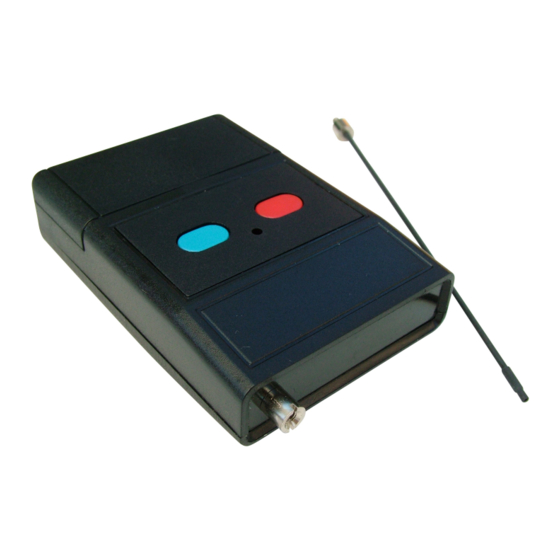
ANTENNA INSTALLATION.
This one is supplied with the module and it has to be installed before to emit.
The inferior part of the antenna includes a metallic piece with a screw. Place and screw it on the module basis, reserved to this
application. See Fig.1 .Do never use a tool to screw this union and avoid ant excessive pressure.The pressure make by your finger will
be enough to adjust both pieces.
The TL-14' s antenna is made with flexible steel, nevertheless, don't fold the antenna, in right position.
Don't use any other antenna type, different than supplied one. If the supplied one will be damaged, contact your CEBEK distributor and
ask for a new original. If you don't respect this point, the module doesn't properly work and the module's warranty will be cancelled.
OPERATING MODE
TO CONFIGURE SECURITY CODE.
this reason, they includes a micro-switches battery composed by 8 trinary switches, allowing to configure a security code, which make
the difference and exclusivity of each module.
To adjust the micro-switches battery, firstly you have to remove the cover of the battery connector. See paragraph "Battery " change to
correctly do this operation.
Once the micro-switches battery discovered, you have to check the position of 8 witches, each one could be placed in three different
position: "-";"0"; and "+". Change the original position (supplied form factory), moving ands electing you own personal code. Don't
forget that the emitter's configuration has to be the same than the receiver. If you don't insert the same code, the communication
between them will be impossible.
The micro-switches battery allows to establish till 13.122 combinations, which will make the difference between your emitter and
others with similar characteristics. Once the code selected and all connection in the receiver done, you only have to press one of push
buttons and see how the corresponding output is connected. The Led will intermittently light till you maintain pressed the push button,
to indicate that it is emitting. If the Led doesn't light, check the battery position, if the polarity is correct, or if it is not discharged.
Don't press at the same time both push buttons, the emitter will only emit a single signal from on of them. If you wish to connect at the
same time both outputs in the receiver, or if you wish to exclusively assign one of two push buttons to a one channel receiver, check
the corresponding paragraph in the Instruction manual of the se modules.
Voltage...........................................................................12VDC Battery (type A23).
Minimum consumption (without emission).....................0mA.
Maximum Consumption, (emitting)................................12,7mA.
Emission frequency ......................................................433,92MHz.
Antenna length...............................................................148mm.
Sizes, (without antenna).................................................90x60x24mm.
Maximum reach .............................................................300m.
Protection against inversion polarity, (P.I.P.)...................Yes.
The TL-14 module requires an antenna to emit with the maximum power and efficiency.
All CEBEK Remote Control work with the regulated European Frequency 433,92 MHz. For
www.cebek.com
EMITTER R.F.
TECHNICAL CHARACTERISTICS
-
sat@cebek.com
TL-14
Advertisement
Table of Contents

Summary of Contents for Fadisel Cebek TL-14
- Page 1 EMITTER R.F. TL-14 TECHNICAL CHARACTERISTICS Voltage................12VDC Battery (type A23). Minimum consumption (without emission).....0mA. Maximum Consumption, (emitting)........12,7mA. Emission frequency ............433,92MHz. Antenna length...............148mm. Sizes, (without antenna)..........90x60x24mm. Maximum reach .............300m. Protection against inversion polarity, (P.I.P.)....Yes. The two channels R.F Emitter TL-14, allows to emit an signal till approximately 300 m omnidirectional. This signal could be recognised and executed by an y CEBEK radiofrequency (R.F) receivers, with one or two channels of de Group 1 The security code could be configured between 13.122 different combinations.
- Page 2 TL-14 HOW TO OPEN THE ENCLOSURE AND SUBSTITUTE THE BATTERY. The TL-14 enclosure could be opened pressing to the outside the removable enclosure cover. See the drawing. With the front cover, removed from the rest of the enclosure, you could accede to the battery and micro-switches battery. The new battery has to be identical than the previous one: 12 V and A 23 type.
Need help?
Do you have a question about the Cebek TL-14 and is the answer not in the manual?
Questions and answers