Table of Contents
Advertisement
Quick Links
1HDB 050016-YN-A
Two-Column Rotary Disconnector
Type SGF
Instruction Manual
Optionally with built on
Earthing Switch Type TEC
Rated Voltages : 36 - 362kV
Rated Current : 1600 - 3150 A
Advertisement
Table of Contents

Related Manuals for ABB SGF


Summary of Contents for ABB SGF
- Page 1 1HDB 050016-YN-A Two-Column Rotary Disconnector Type SGF Instruction Manual Optionally with built on Earthing Switch Type TEC Rated Voltages : 36 - 362kV Rated Current : 1600 - 3150 A...
- Page 2 1HDB 050016-YN-A Contents Please Read First................1 Copyright ................1 Guarantee................1 Conventions................1 Function ..................2 Disconnector ................2 Earthing Switch ..............2 Variants.................. 2 Mounting Alternatives ..............3 Parallel Arrangement of Disconnector Poles ......3 Series Arrangement of Disconnector Poles ......Basic Design ..................
- Page 3 1HDB 050016-YN-A Mounting of Operating Mechanism For Earthing Switch ..............44 13.1 Direct Mounting ..............44 13.2 Separate Mounting ............... 46 Mounting of Earthing Switch ............54 14.1 Earthing Switch Poles in Parallel ........... 54 14.2 Earthing Switch Poles in Series And Mounting on Individual Disconnector Poles ....
- Page 4 Figure 2 : 3-pole type SGF two-column rotary disconnector In series arrangement (basic design) ........3 Figure 3 : Basic design of type SGF two-column rotary disconnector ..4 Figure 4 : Basic design of earthing switch ..........5 Figure 5 :...
- Page 5 1HDB 050016-YN-A Figure 24 : Mounting of operating mechanism for disconnector, Separate mounting if measurement m3 = 6 ... 12 m : Details A and detail B .............. 30 Figure 25 : Mounting of operating mechanism for disconnector, Separate mounting : Laterally offset operating mechanism ..31 Figure 26 : Mounting of operating mechanism for disconnector, Separate mounting : Mounting of operating lever (74)
- Page 6 1HDB 050016-YN-A Figure 45 : Mounting of earthing switch, earthing switch poles in parallel : Mounting of earthing switch link (336) ........56 Figure 46 : Mounting of earthing switch, earthing switch poles in parallel : Mounting of earthing connections (79, 343), detail 1 and detail 2 : Two earthing connections for rated short-time currents >...
- Page 7 1HDB 050016-YN-A Figure 59 : Mounting of earthing switch, earthing -switch poles in series : Mounting of earthing -switch lever (19) and operating rod (71) if operating mechanism for earthing switch on finger side ..........71 Figure 60 : Mounting of earthing switch, earthing-switch poles in series : Adjustment of operating mechanism for earthing switch if operating mechanism for earthing switch on contact side ..
- Page 8 © ABB Calor Emag Schaltanlagen AG 1994. Guarantee If these service instructions are followed, this will, in our experience, guarantee the safe and reliable operation of our products.
- Page 9 Outdoor installation and formation of groups The type SGF two column rotary disconnector described in these service instructions is a single - pole disconnector for outdoor installation. Two or three poles can be coupled to form a group.
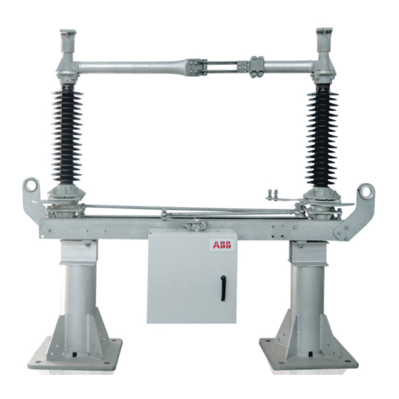
- Page 10 Note : The side for mounting the operating mechanism is finalized with the order. Later changes are not possible. Parallel Arrangement of Disconnector Poles Figure 1 shows a 3-poles type SGF two-column rotary disconnector with two earthing switches in parallel arrangement. Figure 1 : 3-pole type SGF two-column rotary disconnector in parallel arrangement (basic design)
- Page 11 4/113 Basic Design Disconnecetor Figure 3 and Table 1 contain the most important components of the type SGF two-column rotary disconnector. Figure 3 : Basic design of type SGF two-column rotary disconnector Table 1 : Basic design of type SGF two-column rotary disconnector Designation Item No.
- Page 12 1HDB 050016-YN-A 5/113 Earthing - Switch Figure 4 and Table 2 contain the most important components of the earthing switch. Figure 4 : Basic design of earthing switch Table 2 : Basic design of earthing switch Designation Item No. Remarks Earthing connection 79 Cu, flexible Earthing-switch shaft...
- Page 13 6/113 Mode of Operation General The type SGF two-column rotary disconnector has separate operating mechanisms for the disconnector and the earthing switch. Prevention of automatic operating or closing When the equipments switched on or off, a dead-center position is passed through just before the end positions are reached.
- Page 14 1HDB 050016-YN-A 7/113 Earthing Switch Figure 6 : Mode of operation of earthing switch (example : 3-pole in parallel arrangement) Operating mechanism :- The operating mechanism (77) of the earthing switch transfers the operating energy via the operating rod (71) to the earthing-switch shaft (337). The tubular contact arm (23) swivels up (ON) or down (OFF).
- Page 15 General Electrical Data Note : The precise electrical data is contained in the data sheets supplied. The data in Table 3 contains of standard values. Table 3 : General electrical data of type SGF two-column rotary disconnector (standard values) Rated voltage 72.5...
- Page 16 Note : The precise dimensions are contained in the dimensions drawings supplied. The dimensions in Table 5 are standard values. Figure 7 : General main dimension of SFG two-column rotary disconnector Table 5 : General main dimensions of type SGF two-column rotary disconnector (standard values) Rated voltage 72.5...
- Page 17 1HDB 050016-YN-A 10/113 Minimum Distance between Disconnector Poles Note : The precise dimensions are contained in the dimension drawing supplied. The dimensions in Table 6 are standard values. Table 8 : Minimum distances Pmin between poles of disconnector in parallel arrangement Figure 9 : Minimum distances Pmin between poles of disconnector in series arrangement Table 6 : Minimum distances P between poles of disconnector in series and parallel arrangement...
- Page 18 1HDB 050016-YN-A 11/113 Scope of Supply Note : The disconnector is supplied in components Disconnector The scope of supply does not include the fixing materials for mounting the disconnector on the supporting structures. The components supplied comprises : Disconnector base (2) consisting of : Sectional-steel base frame (221), rotary pedestals (70), diagonal rod (68), disconnector operating lever (69), connecting lever (3) and transportation angle (328) Figure 13...
- Page 19 1HDB 050016-YN-A 12/113 Earthing Switch The supply of the earthing switch comprises. Earthing-switch links (336) Tubular contact arms (23) wiwth contact finger (20) and T-type clamp(329) Earthing contact (18) Operating mechanism for earthing switch (77) Operating rod (37) Operating lever (76) with clamping cover (334) Earthing connections (79) For 2nd earthing switch : earthing connections (343) Earthing - switch shaft (337)
- Page 20 1HDB 050016-YN-A 13/113 Shipping and Storage Shipping The equipment is shipped on pallets (Germany) or in boxes (outside Germany) Note : After unpacking, check all supplied equipment immediately for shipping damage. Report shipping damage without delay to the forwarding agency. Storage Caution : In the case of inappropriate storage of the individual components, there is the risk of ingress of water.
- Page 21 1HDB 050016-YN-A 14/113 Mounting, General The type SGF two-column rotary disconnector can be mounted in two positions Horizontal (standard) Vertical (must be expressly specified when ordering and is only possible for rated voltage < 170 kV) Note : For vertical mounting of the disconnector, you require the additionally supplied documents.
- Page 22 1HDB 050016-YN-A 15/113 Treatment of contact Surfaces and Intersection Surfaces Caution : Bolted or sliding contact surfaces that conduct current have an effect on the electrical resistance of the current path. Dirty or oxidized contact surfaces increase the electrical resistance. This may result in irreparable damage to equipment., The following regulations must be observed.
- Page 23 Caution : The diagonal rods (68) Figure 13 have been adjusted at the factory for the precise engagement of the main contacts. The adjustment may only be changed by ABB-trained specialist erectors. Mounting steps :...
- Page 24 1HDB 050016-YN-A 17/113 Finger side (FS) Contact side (KS) Figure 12 : Mounting of disconnector : Shipping of disconnector base (2) if mounting on supporting structure Finger side (FS) Contact side (KS) Figure 13 : Mounting of disconnector : Shipping of premounted disconnector pole if mounting in front of supporting structure (example : Version for rated normal current 1 600 A)
- Page 25 1HDB 050016-YN-A 18/113 Item numbers 400-... : IEC support insulators Item numbers 401-... : DIN support insulators Finger side (FS) Contact side (KS) Rated voltage 1000 72.5 1000 1400 1650 1830 2620 2620 3200 Finger side (FS) Contact side (KS) Figure 14 : Mounting of disconnector...
- Page 26 1HDB 050016-YN-A 19/113 Item numbers 400-... : IEC support insulators Item numbers 401-... : DIN support insulators Finger side (FS) Contact side (KS) Figure 15 : Mounting of disconnector : Mounting of corona-protection fittings (87) on rotary heads (only for rated voltages 300kV & 362 kV)
- Page 27 1HDB 050016-YN-A 20/113 Figure 16 : Mounting of disconnector : Mounting of corona-protection fittings (7) on finger side (only for rated voltages 245kV ..362 kV)
- Page 28 1HDB 050016-YN-A 21/113 Figure 17 : Mounting of disconnector : Mounting of corona-protection fittings (7) on contact side (only for rated voltages 245kV ..362 kV)
- Page 29 1HDB 050016-YN-A 22/113 Mounting of Operating Mechanism for Disconnector Note : The mounting side of the operating mechanism is apparent from the position of the disconnector operating lever (69) Figure 18.The pole on which the operating mechanism is mounted can be freely selected.
- Page 30 1HDB 050016-YN-A 23/113 Figure 18 : Mounting of operating mechanism for disconnector : Direct mounting...
- Page 31 1HDB 050016-YN-A 24/113 Figure 19 : Mounting of operating mechanism for disconnector, direct mounting : Mounting of operating lever (74) if operating mechanism for disconnector at opening side.
- Page 32 1HDB 050016-YN-A 25/113 Figure 20 : Mounting of operating mechanism for disconnector, direct mounting : Mounting of operating lever (74) if operating mechanism for disconnector at opposite opening side.
- Page 33 1HDB 050016-YN-A 26/113 11.2 Separate Mounting In case of separate mounting of the operating mechanism for the disconnector, the mounting steps are dependent on measurement m3 of operating shaft (43) A Figure 22, Figure 23 and a possible lateral offset of operating mechanism and disconnector A Figure 25 : Separate mounting if measurement m3 <...
- Page 34 1HDB 050016-YN-A 27/113 Motor-operated mechanism Manual operating mechanism Figure 21 : Mounting of operating mechanism for disconnector, separate mounting : Measurement m3 < 6 m...
- Page 35 1HDB 050016-YN-A 28/113 Figure 22 : Mounting of operating mechanism for disconnector, separate mounting if measurement m3 < 6 m : Mounting dimensions...
- Page 36 1HDB 050016-YN-A 29/113 Figure 23 : Mounting of operating mechanism for disconnector, separate mounting if measurement m3 = 6 ... 12 m : Mounting dimensions (Details A And Detail B : Figure 24)
- Page 37 1HDB 050016-YN-A 30/113 Figure 24 : Mounting of operating mechanism for disconnector, separate mounting if measurement m3 = 6 ... 12 m : Detail A and Detail B...
- Page 38 1HDB 050016-YN-A 31/113 Figure 25 : Mounting of operating mechanism for disconnector, separate mounting : Laterally offset operating mechanism...
- Page 39 1HDB 050016-YN-A 32/113 Figure 26 : Mounting of operating mechanism for disconnector, separate mounting : Mounting of operating lever (74) if operating mechanism for disconnector at opening side...
- Page 40 1HDB 050016-YN-A 33/113 Figure 27 : Mounting of operating mechanism for disconnector, separate mounting : Mounting of operating lever (74) if operating mechanism for disconnector at opposite opening side...
- Page 41 1HDB 050016-YN-A 34/113 Mounting of Coupling of Disconnectors, Cabling Caution : For rated voltages 245 ... 362 kV : If the disconnector poles are arranged in parallel, the coupling rods (15) must always be mounted on the same side on which the earthing switch is mounted Note : Make sure that the disconnector poles are in the ON position before coupling and that the transportation angles (328) are still mounted.
- Page 42 1HDB 050016-YN-A 35/113 Item numbers 400-... : IEC support insulators Item numbers 401-... : DIN support insulators Figure 28 : Mounting of coupling of disconnectors : Overview...
- Page 43 1HDB 050016-YN-A 36/113 Figure 29 : Mounting of coupling of disconnectors : Disconnector poles in parallel...
- Page 44 1HDB 050016-YN-A 37/113 Figure 30 : Mounting of coupling of disconnectors : Disconnector poles in series...
- Page 45 1HDB 050016-YN-A 38/113 Item numbers 420-... : Direct mounting Item numbers 422-... : Separate mounting Figure 31 : Mounting of coupling of disconnectors : Mounting of operating rod (37) if operating mechanism for disconnector at opening side...
- Page 46 1HDB 050016-YN-A 39/113 Item numbers 420-... : Direct mounting Item numbers 422-... : Separate mounting Figure 32 : Mounting of coupling of disconnectors : Mounting of operating rod (37) if operating mechanism for disconnector at opposite opening side...
- Page 47 1HDB 050016-YN-A 40/113 Item numbers 420-... : Direct mounting Item numbers 422-... : Separate mounting Rated voltage R (U = 100 mm) R (U = 150 mm) 72.5 83 + 1 1 222 1 222 Figure 33 : Mounting of coupling of disconnectors : Adjustment of operating mechanism for disconnector if operating mechanism for disconnector at opening side...
- Page 48 1HDB 050016-YN-A 41/113 Item numbers 420-... : Direct mounting Item numbers 422-... : Separate mounting Rated voltage R (U = 10 mm) R (U = 50 mm) 72.5 83 + 1 1 222 1 222 Figure 34 : Mounting of coupling of disconnectors : Adjustment of operating mechanism for disconnector if operating mechanism for disconnector at opposite opening side...
- Page 49 1HDB 050016-YN-A 42/113 K=(55+5)mm for Disconnectors upto 300 kV K=(95+5)mm for Disconnectors 362 kV & above Figure 35 : Mounting of coupling of disconnectors : Disconnector main contacts, engagement...
- Page 50 1HDB 050016-YN-A 43/113 Figure 36 : Mounting of coupling of disconnectors : Disconnector main contacts, adjusting measurements...
- Page 51 1HDB 050016-YN-A 44/113 Mounting of Operating Mechanism for Earthing Switch 13.1 Direct Mounting Note : Make sure that the operating mechanism is in the ON position (as-delivered state). If the operating mechanism is in the OFF position, set it to the ON position using the emergency hand crank (39).
- Page 52 1HDB 050016-YN-A 45/113 Figure 37 : Mounting of operating mechanism for earthing switch : Direct mounting...
- Page 53 1HDB 050016-YN-A 46/113 13.2 Separate Mounting In case of separate mounting of operating mechanism for earthing switch, the mounting steps are dependent on measurement m3 of operating shaft (43) Figure 39, Figure 40 and on a possible offset of operating mechanism and earthing switch Figure 42 : •...
- Page 54 1HDB 050016-YN-A 47/113 Figure 38 : Mounting of operating mechanism for earthing switch, separate mounting : Measurement m3 < 6 m...
- Page 55 1HDB 050016-YN-A 48/113 Figure 39 : Mounting of operating mechanism for earthing switch, separate mounting if measurement m3 < 6 m : Mounting dimensions...
- Page 56 1HDB 050016-YN-A 49/113 Figure 40 : Mounting of operating mechanism for earthing switch, separate mounting if measurement m3 = 6 ... 12 m : Mounting dimensions (Details A and Details B : Figure 41)
- Page 57 1HDB 050016-YN-A 50/113 Figure 41 : Mounting of operating mechanism for earthing switch, separate mounting if measurement m3 = 6 ... 12 m : Detail A and Detail B...
- Page 58 1HDB 050016-YN-A 51/113 Figure 42 : Mounting of operating mechanism for earthing switch, separate mounting : Laterally offset operating mechanism...
- Page 59 1HDB 050016-YN-A 52/113 Figure 43 : Mounting of operating mechanism for earthing switch, direct and separate mounting : Mounting of operating lever (76) if operating mechanism for earthing switch on contact side.
- Page 60 1HDB 050016-YN-A 53/113 Figure 44 : Mounting of operating mechanism for earthing switch, direct and separate mounting : Mounting of operating lever (76) if operating mechanism for earthing switch on finger side.
- Page 61 1HDB 050016-YN-A 54/113 Mounting of Earthing Switch Note : If you suspect shipping damage, check the spacing dimensions of contact fingers (20) Figure 69, Figure 70. 14.1 Earthing Switch Pole in Parallel Note : Make sure that the disconnector poles are in the OFF position before mounting the earthing switches Mounting steps Grease clamps sleeves (433-353, 434-353)
- Page 62 1HDB 050016-YN-A 55/113 Mounting steps (continued) : Shorten operating rod (71) so that, during a manual test operation, all the rear contact fingers are up against the stop in the ON position. Check distance between contact finger (20) and stop (21). the distance on one pole of 3-pole group must not be more than 5 mm Figure 64 If necessary, correct the contact of the contact fingers by adjusting operating rod (71) and check...
- Page 63 1HDB 050016-YN-A 56/113 Item numbers 433-... : Poles Distance P < 2 500 mm Item numbers 434-... : Pole distance P > 2 500 mm Figure 45 : Mounting of earthing switch, earthing-switch poles in parallel : Mounting of earthing-switch link (336)
- Page 64 1HDB 050016-YN-A 57/113 Figure 46 : Mounting of earthing switch, earthing-switch poles in parallel : Mounting of earthing connections (79, 343). Detail 1 and Detail 2 : Two earthing connections for rated short-time currents > 40 kA, 1 sec.
- Page 65 1HDB 050016-YN-A 58/113 Figure 47 : Mounting of earthing switch, earthing-switch poles in parallel : Spacing dimensions...
- Page 66 1HDB 050016-YN-A 59/113 Figure 48 : Mounting of earthing switch, earthing-switch poles in parallel : Mounting of coupling piece (342, 334) for connection of earthing-switch shafts (337) for pole distances P > 2 500 mm...
- Page 67 1HDB 050016-YN-A 60/113 Item numbers 421-... : Direct mounting Item numbers 423-... : Separate mounting Figure 49 : Mounting of earthing switch, earthing-switch poles in parallel : Mounting of earthing-switch lever (19) and operating rod (71) if operating mechanism for earthing switch on contact side...
- Page 68 1HDB 050016-YN-A 61/113 Item numbers 421-... : Direct mounting Item numbers 423-... : Separate mounting Figure 50 : Mounting of earthing switch, earthing-switch poles in parallel : Mounting of earthing-switch lever (19) and operating rod (71) if operating mechanism for earthing switch on finger side...
- Page 69 1HDB 050016-YN-A 62/113 W = 132 mm for Disconnector of 123,145,170,245,300 & 362 kV W = 108 for 36 kV W = 120 for 72.5 kV Rated Voltage S (U = 100 mm) S (U = 100 mm) Y1 (U = 100 mm) Y2 (U = 100 mm) 90.5+1 140+1...
- Page 70 1HDB 050016-YN-A 63/113 Rated Voltage S (U = 100 mm) S (U = 100 mm) Y1 (U = 100 mm) Y2 (U = 100 mm) 109.5+1 159.5+1 72.5 110.5+1 160.5+1 1 077 1 472 111.5 + 1 161.5 + 1 50 + 5 100 + 5 1 472...
- Page 71 1HDB 050016-YN-A 64/113 14.1 Earthing Switch Poles in Series and Mounting on Individual Disconnector Poles Note : Make sure that the disconnector poles are in the OFF position before mounting the earthing switches Mounting steps Grease clamps sleeves (43 -353, 43 -353) with silicone grease Figure Place earthing-switch links (336) or base frame of earthing switch (336a) into mounting position...
- Page 72 1HDB 050016-YN-A 65/113 Mounting steps (continued) : If necessary, correct the contact of all contact fingers on the operated pole by adjusting operating rod (71) and check by means of test operation Tighten lock nuts on operating rod (left-, right-hand thread) Figure 60, Figure 61 Correct the contact of the contact fingers on the coupled poles by adjusting coupling rods (15) and check by means of test operation...
- Page 73 1HDB 050016-YN-A 66/113 Item numbers 433-... : 3-pole version, pole distance P < 2 500 mm Item numbers 434-... : 3-pole version, pole distance P > 2 500 mm Item numbers 431-... : 1-pole version or 2-pole version in parallel Item numbers 436-...
- Page 74 1HDB 050016-YN-A 67/113 Figure 54 : Mounting of earthing switch, earthing-switch poles in series : Mounting of earthing connection (79, 343). Detail 1 and Detail 2 : Two earthing connections for rated short-time currents > 40 kA, 1 sec...
- Page 75 1HDB 050016-YN-A 68/113 Figure 55 : Mounting of earthing switch, earthing-switch poles in series : Mounting of coupling rods (15)
- Page 76 1HDB 050016-YN-A 69/113 Figure 56 : Mounting of earthing switch, earthing-switch poles in series : Adjusting measurements for earthing-switch shaft (73), and earthing-switch lever (339), earthing switch on finger side Figure 57 : Mounting of earthing switch, earthing-switch poles in series : Adjusting measurements for earthing-switch shaft (73) and earthing-switch lever (339), earthing switch on contact side...
- Page 77 1HDB 050016-YN-A 70/113 Item numbers 421-... : Direct mounting Item numbers 423-... : Separate mounting Figure 58 : Mounting of earthing switch, earthing-switch poles in series : Mounting of earthing-switch lever (19) and operating rod (71) if operating mechanism for earthing switch on contact side...
- Page 78 1HDB 050016-YN-A 71/113 Item numbers 421-... : Direct mounting Item numbers 423-... : Separate mounting Figure 59 : Mounting of earthing switch, earthing-switch poles in series : Mounting of earthing-switch lever (19) and operating rod (71) if operating mechanism for earthing switch on finger side...
- Page 79 1HDB 050016-YN-A 72/113 Rated Voltage S (U = 100 mm) S (U = 100 mm) Y1 (U = 100 mm) Y2 (U = 150 mm) 90.5+1 140+1 72.5 89.5+1 139.5+1 1 077 88.5 + 1 138.5 + 1 80 + 5 130 + 5 1 472 1 472...
- Page 80 1HDB 050016-YN-A 73/113 Rated Voltage S (U = 100 mm) S (U = 100 mm) Y1 (U = 100 mm) Y2 (U = 150 mm) 109.5+1 159.5+1 72.5 110.5+1 160.5+1 1 077 111.5 + 1 161.5+1 50 + 5 100 + 5 1 472 1 472 Figure 61 : Mounting of earthing switch, earthing-switch poles in series : Adjustment of operating mechanism...
- Page 81 1HDB 050016-YN-A 74/113 Figure 62 : Mounting of earthing switch : Mounting of earthing contact (18) for rated voltages 36 ... 170 kV and rated peak-with-stand currents < 100 kA Figure 63 : Mounting of earthing switch : Mounting of earthing contact (18) for rated voltages 245 ... 362 kV or rated peak-with-stand currents >...
- Page 82 1HDB 050016-YN-A 75/113 I = distance between rear contact finger (20) and stop (21) of earthing contact (18) Rated voltage 245 ... 362 kV, Rated voltage 36 ... 170 kV, and rated peak - withstand current > 100 kA and rated peak - withstand current < 100 kA I (recommended presetting on poles a, b, c during mounting) I (after Pole distance...
- Page 83 1HDB 050016-YN-A 76/113 Mounting of Mechanical Interlocking Caution : The interlocking segments, the operating mechanism for the disconnector and the operating mechanism for the earthing switch must be mounted together on one pole. For rated voltages 245 ... 362 kV : If the disconnector poles are arranged in parallel, the coupling rods (15) must always be mounted on the same side on which the earthing switch is mounted.
- Page 84 1HDB 050016-YN-A 77/113 Item number 289 : Only for rated voltage 245 ... 362 kV and earthing switch on contact side (KS) Switching state : Disconnector ON Earthing switch OFF Switching state : Disconnector OFF Earthing switch ON Detail 1 Figure 65 : Mounting of mechanical interlocking : Adjusting measurement of mechanical interlocking between disconnector and earthing switch...
- Page 85 Commissioning of Disconnector Caution : The diagonal rods (68) are adjusted at the factory for precise engagement of the main contacts. The adjustment may only be changed by ABB-trained specialist erectors. Commissioning Agent Carry out a test operation manually, checking that there is satisfactory contact engagement of...
- Page 86 16.5 De-commissioning The type SGF two-column rotary disconnector is an environmentally friendly product. If the herein-described switching device is de-commissioned, the materials remove should be reused. The switching device can be disposed of in an environmentally friendly manner on the basis of the existing legal regulations.
- Page 87 1HDB 050016-YN-A 80/113 Maintenance Caution : We recommend that the inspection intervals given in Table 8 for normal and extreme ambient conditions be complied with. They are essential to the trouble-free operation of the equipment. Warning : In the case of work on high-voltage equipment, there is danger to life if the applicable safety rules are not observed and complied with.
- Page 88 1HDB 050016-YN-A 81/113 17.1 Treatment of Contact Surfaces and Intersection Sufaces Caution : Bolted or sliding contact surfaces that conduct current have an effect on the electrical resistance of the current path. Dirty or oxidized contact surfaces increase the electrical resistance. This may result in irreparable damage to equipment.
- Page 89 1HDB 050016-YN-A 82/113 17.2 Disconnector Warning : In the case of work on high-voltage equipment, there is danger to life if the applicable safety rules are not observed and complied with. The safety rules also include the five safety rules according to DIN/VDE 0105 Part 1 The five safety rules according to DIN/VDE Disconnection Safeguard against reconnection...
- Page 90 1HDB 050016-YN-A 83/113 Figure 66 : Maintenance of disconnector : Replacement of contact fingers (66) and contact pieces (67)
- Page 91 1HDB 050016-YN-A 84/113 17.3 Earthing Switch Warning : In the case of work on high-voltage equipment, there is danger to life if the applicable safety rules are not observed and complied with. The safety rules also include the five safety rules according to DIN/VDE 0105 Part 1 The five safety rules according to DIN/VDE Disconnection Safeguard against reconnection...
- Page 92 1HDB 050016-YN-A 85/113 Figure 67 : Maintenance of earthing switch : Replacement of earthing contact (18) for rated voltages 36 ... 170 kV and rated peak-withstand currents < 100 kA.
- Page 93 1HDB 050016-YN-A 86/113 Figure 68 : Maintenance of earthing switch : Replacement of earthing contact (18) for rated voltage 245 ... 362 kV or rated peak-withstand currents > 100 kA.
- Page 94 1HDB 050016-YN-A 87/113 Figure 69 : Maintenance of earthing switch : Contact finger dimensions for rated voltages 123 ... 170 kV and rated peak-withstnad currents < 100 kA Figure 70 : Maintenance of earthing switch : Contact finger dimensions for rated voltages 245 ... 362 kV or rated peak-withstand currents >...
- Page 95 1HDB 050016-YN-A 88/113 Instructions for Assembling Adapter Plate (Reference : Service Instruction Manual GPDT 069622a E, Fig:14, Page : 18) Remove adapter, which is assembled with rotating flange (70) on the frame assembly(221) Remove fasteners from the adapter plate supplied. Insert M16 screw (discard M16 nuts supplied) along with washers into adopter plate hole and engage in the hole of bottom flange of insulator as shown in Fig : 1 Tighten all screws with torque of 174Nm.
- Page 96 1HDB 050016-YN-A 89/113 Fig. 72 : Rotational Alignment of contact fingers (66) for Perfect Contact on Contact Piece (67) In case Fingers are found to be not getting properly alignment with the conhtact Piece (67), Then following steps are to be followed. Loosen the Fasteners Allow the Complete finger assembly to rotate the extent required to take its self aligned position with respect to Contact Piece (67)
- Page 97 1HDB 050016-YN-A 90/113 Figure 73 : Tilting of Column for alignment When it is required to tilt the complete pole columns any direction for proper clearances, alignment etc. follow the following steps. Just Loosen the check nuts, Tilt the Pole in the direction needed by rotating these nuts either in clockwise or anti-clockwise direction.
- Page 98 + 1E ......Number of earthing switches per pole Example of an order number An example of the order number on the rating plate of a type SGF two-column rotary disconnector is GP 251 2130 04 c. The individual parts of this designation have the following significance : •...
- Page 99 Note : The quantities given in the following tables apply to each pole. For two or more poles, increase the quantity accordingly. Table 10 : List of spare parts for type SGF two-column rotary disconnector. Designation of spare part Qty.
- Page 100 1HDB 050016-YN-A 93/113 List of Item Numbers 19.1 Item Numbers Note : The numbers in parentheses in the "Remarks" column are also item numbers. These numbers also appear as item numbers in the first column in the list. No. Description Remarks Foundation, supporting structure, support Onsite...
- Page 101 1HDB 050016-YN-A 94/113 Description Remarks T-type clamp Tubular contact arm (23) Thrust bearing Earthing-switch link, earthing-switch shaft (73) Collared bush Earthing-switch link, earthing-switch shaft (73) Spacer Earthing connection (79) Disconnector pole assy Only for deliveries in Germany Clamping cover Operating lever (74, 76), earthing-switch lever (19), separate mounting of operating mechanism Coupling piece Operating shaft (43), separate mounting of...
- Page 102 1HDB 050016-YN-A 95/113 19.2 Connecting Sets Connecting sets are included in the scope of supply. If necessary, connecting sets can be re-ordered from us. Order Information To ensure speedy processing of your order, we need to know the item number and the order number of the connecting set you require.
- Page 103 1HDB 050016-YN-A 96/113 Item No. 421, Order No. : GPDT 06 0004 R56 Connecting set, (motor-operated) mechanism, earthing switch (mounting, operating mechanism and operating linkage Items No. Description Size Qty. Standard 421-303 Hexagon screw M16x60 DIN 933 8.8-tzn 421-306 Hexagon screw M16x30 DIN 933 8.8-tzn 421-323...
- Page 104 1HDB 050016-YN-A 97/113 Item No. 431, Order No. GPDT 06 4000 R61 Connecting set, mounting, earthing switch, 1-pole and parallel arrangement, 2-pole. (fixing, earthihng-switch links, earthing-switch shaft and flexible connections) Items No. Description Size Qty. Standard 431-305 Hexagon screw M12x45 DIN 933 8.8-tzn 431-309 Hexagon screw...
- Page 105 1HDB 050016-YN-A 98/113 Item No. 435, Order No. GPDT 06 4000 R66 Connecting set, earthing switch, series arrangement, 2-pole (fixing, earthihng-switch links, earthing-switch shaft and flexible connections) Items No. Description Size Qty. Standard 435-305 Hexagon screw M12x45 DIN 933 8.8-tzn 435-309 Hexagon screw M10x35sp...
- Page 106 1HDB 050016-YN-A 99/113 Item No. 439, Order No. GPDT 06 0004 R39 Connecting set, separate mounting of operating mechanism (for collared bush and coupling piece) Items No. Description Size Qty. Standard 439-302 Hexagon screw M10x35sp DIN 933 A2-70 439-305 Hexagon screw M16x110 DIN 933 8.8-tzn 439-324...
- Page 107 1HDB 050016-YN-A 100/113 Index Address, 104 Ambient conditions, 80 Bag with desiccative, 78 Base frame, 7, 11, 16, 90 Base-frame length, 9 Of earthing switch, 64, 91 Catching hook, 90 Clamp sleeve, 55, 65 Earthing-switch link, 54, 64 on operating rod 83, 90 Clamping cover, 11,12,76, 91 Collared bush, 26, 46, 54, 64, 91 Separate mounting m3 = 6 ...
- Page 108 1HDB 050016-YN-A 101/113 Dead-center position, 6, 78 Dead-center position, 34 Diagonal rod, 6, 11, 16, 78, 90 Disconnector base, 4, 11, 16, 17, 90 Disconnector operating lever, 11 Disconnector operating lever for operating mechanism, 90 Distances in contact zone, 34, 43 Driving plate, Separate mounting M3 = 6 ...
- Page 109 1HDB 050016-YN-A 102/113 Main dimensions, 9 Measurement m1, 26, 46 Measurement m3, 26, 27, 28, 29, 30, 46, 47, 48, 49, 50 Minimum distances between poles, 10 Mounting side of operating mechanism, 22 Offset bearing. 12. 46. 91 Operating lever Disconnector, 11, 22, 25, 26, 32, 33, 34, 78, 90 Earthing switch, 12, 44, 46, 52, 53, 54, 64, 78 ,90 Spacing dimensions, 54, 64...
- Page 110 1HDB 050016-YN-A 103/113 Support insulator, 4, 6, 11, 16, 82, 90 Insulator height, 9 Minimum breaking load, 8 Support-insulator distance, 9 Switching time, 78 T-type clamp, 12, 54, 64, 91 Fixing bolt for, 55, 65, 78, 91 Hole through, 55, 65 Technical data Electrical, 8 Mechanical, 8...
- Page 111 We are always at pains to improve the quality of our documentation. For this reason, we are very interested in any comments you may have on the present ABB Limited documentation. Please complete this form if you have found any missing or...
- Page 112 1HDB 050016-YN-A 105/113 Space for further comments :...
- Page 113 "ABB is woking continuously to improve the products. We therefore reserve the right to change designs, dimensions data without prior notice." ABB Limited For Overseas Inquiries Maneja Works Maneja Works Maneja, Vadodara - 390 013 Maneja, Vadodara - 390 013...
- Page 114 1 HDU 05004-YN Rev. C Motor Operated Mechanisms Types MT50 and MT100 Instruction Manual...
- Page 115 1 HDU 05004-YN Rev. C 2/16 For High-Voltage Disconnectors and Earthing Switches for Outdoor Installation Table of Contents Description Page General Remarks Design Optional Extras Method of Operation Technical Data Transportation and Storage Installation Commissioning Maintenance Spare Parts List of Components...
- Page 116 1 HDU 05004-YN Rev. C 3/16 General remarks Practical experience has shown that strict adherence to the recommendation of this instruction manual will ensure the best possible safe performance of the equipment. In an instruction manual it is not possible to cover every possible eventuality that might occur when using technical apparatus.
- Page 117 1 HDU 05004-YN Rev. C 4/16 Unauthorised manual operation is restricted by providing a cover (15) alongwith a padlock arrangement on the door. For manual operation first the front door to be opened after removing the padlock and then cover (15) can be removed for insertion of the manual handle. Ensure blocking magnet (19) (if provided) is energised or pulled up manually.
- Page 118 1 HDU 05004-YN Rev. C 5/16 2, 2a Figure 1 : Inside view of motor-operated mechanisms type MT 50 and MT 100 Motor (with cover 1a) Operating spindle (with cover 2a) and gear-train Auxiliary switch Mounting plate Terminal strip Control contractor Supply lead plate Operating shaft Housing (with door 12a)
- Page 119 1 HDU 05004-YN Rev. C 6/16 Optional Extras (depending on customer’s order) Additional Auxiliary switch contacts upto max. 16 contacts in any combination can be provided. Please refer to schematic drawing submitted against order for details. Caution :- Ensure Auxiliary switch elements positions are not altered if removed for any maintenance.
- Page 120 1 HDU 05004-YN Rev. C 7/16 part 2. A “CLOSED” position signal is given after closing near the top dead center (i.e. after closing of the current path of the disconnector and near top dead center interlocking by the operating linkage) and is cancelled upon opening even before the top dead center is reached (i.e.
- Page 121 1 HDU 05004-YN Rev. C 8/16 Figure 2a Example of internal wiring diagram (MT50 standard design), for motor operation with DC supply.
- Page 122 1 HDU 05004-YN Rev. C 9/16 Figure 2b Example of internal wiring diagram (MT50 standard design), for motor operation with single phase AC supply...
- Page 123 1 HDU 05004-YN Rev. C 10/16 Technical Data Technical data of the motor-operated mechanisms Rated motor voltage 48,110,125,220, 250VDC, 415 VAC Admissible deviation from the rated motor voltage +10% / -15% Rated motor output, short time duty type MT 50 470 W &MT100 Switching time (depending on load)
- Page 124 1 HDU 05004-YN Rev. C 11/16 Technical Data of the Auxiliary Switches Switching capacity of each contact = 2 A at 220 V DC, T = 20 ms Current carrying capacity = 10 A 9.5 ...17.5 9.5 ...17.5 NC contact NO contact Main contact of disconnector...
- Page 125 1 HDU 05004-YN Rev. C 12/16 Commissioning After connecting all cables, first operate the motor operated mechanism with the emergency crank. It is not permitted to use a boring machine instead of the emergency crank. If the disconnector or earthing switch engages properly according to the corresponding operating instructions, the operating mechanism can be actuated electrically.
- Page 126 1 HDU 05004-YN Rev. C 13/16 Spare Parts It is recommeded to keep the following parts in stock so that, in case of disturbances, prolonged periods of interruption are avoided by rapidly replacing the individual parts. When ordering spare parts, indicate the following details : Type and serial number according to the rating plate of the specific unit.
- Page 127 1 HDU 05004-YN Rev. C 14/16 List of Components Item Designation Fig. Motor (with cover 1a) Operating spindle (with cover 2a) and gear-train Auxiliary switch Mounting plate Terminal strip Control contractor Auxiliary pin for emergengy operation Supply lead plate (with earthing connection angle 23 and ventilating hole 16) Operating shaft Anticondensation heater Housing (with door 12a)
- Page 128 1 HDU 05004-YN Rev. C 15/16 Note :...
- Page 129 "ABB is woking continuously to improve the products. We therefore reserve the right to change designs, dimensions data without prior notice." ABB Limited Business Area : Disconnectors Maneja, Vadodara 390 013 India India Tel. : +91-265-2604080 +91-265-2604082/2604261 Fax : +91-265-2638927...
Need help?
Do you have a question about the SGF and is the answer not in the manual?
Questions and answers