Advertisement
Table of Contents
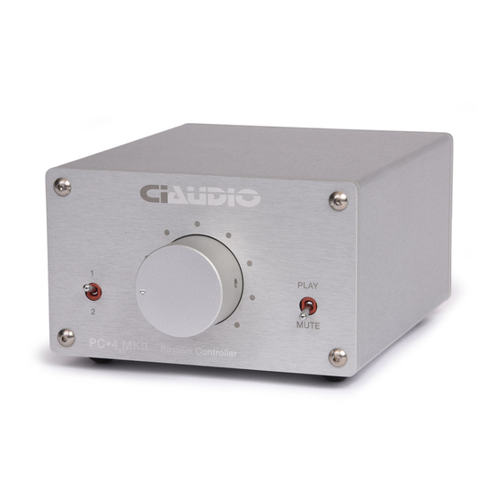
PC●4 MKII Passive Line Controller
Thank you for purchasing the PC●4 MKII Passive Controller.
Design
PC●4 was designed with the audio purist in mind, a minimalist design utilizing the highest quality parts
to yield unmatched transparency.
Similar to previous VPC models, the audio path is completely passive, passing only through an input
switch and potentiometer. For PC●4, we sought only the highest grade components... Cardas Input &
Output jacks, Grayhill hermetically sealed switches with gold over copper contacts, and laser-trimmed
ALPS Blue Velvet potentiometer. Improved layout and 2 layer/3 oz. copper circuit board with improved
layout, all housed in a heavy machined aluminum chassis.
Please read the Configuration section of this document before installing into your playback system.
Advertisement
Table of Contents

Summary of Contents for ci PC-4 MKII
- Page 1 PC●4 MKII Passive Line Controller Thank you for purchasing the PC●4 MKII Passive Controller. Design PC●4 was designed with the audio purist in mind, a minimalist design utilizing the highest quality parts to yield unmatched transparency. Similar to previous VPC models, the audio path is completely passive, passing only through an input switch and potentiometer.
- Page 2 Configuration On the rear panel, there are two pair of stereo INPUTS (1 & 2), and two pair of stereo outputs. Connect your sources to the inputs. Connect your main amplifier to OUTPUT 1. Output 2 can be configured for FIXED or VARIABLE operation (see diagram below). When set to VARIABLE (default), the signal is sent through the volume control and functions identically to OUTPUT 1.
- Page 3 To configure OUTPUT 2 for FIXED, you must first remove the circuit board from its chassis. To disassemble, remove the 8 nuts & washers on the RCA jacks, and also the screw in between them. Then remove the 4 front panel screws. The assembly will now slide out from the front. Move the 2 jumpers from pins 1-2 and place in positions 2-3.
Need help?
Do you have a question about the PC-4 MKII and is the answer not in the manual?
Questions and answers