Table of Contents
Advertisement
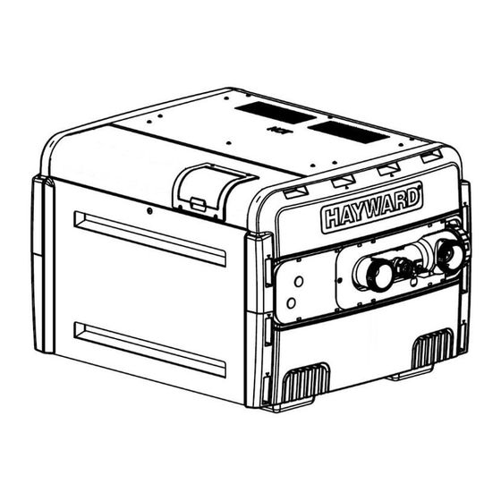
IN GROUND POOL/SPA GAS HEATERS
INSTALLATION & OPERATIONS MANUAL
FOR YOUR SAFETY:
WARNING: If the information in these
instructions is not followed exactly, a fire
or explosion may result causing property
damage, injury, or death.
• Do not store or use gasoline or other
flammable vapors or liquids in the vicinity
of this or any other appliance.
WHAT TO DO IF YOU SMELL GAS:
• Do not try to light any appliance.
• Do not touch any electrical switch; do not
use any phone in your building.
• Immediately call your gas supplier from a
neighbor's phone. Follow the gas supplier's
instructions. If you cannot reach your gas
supplier, call the fire department.
• Installation and service must be performed
by a qualified installer, service agency or
the gas supplier.
This product must be installed and serviced by
authorized personnel, qualified in pool/spa heater
installation. Improper installation and/or operation
can create carbon monoxide gas and flue gases
that can cause serious injury, property damage,
or death.
SAVE THESE
INSTRUCTIONS
CONTENTS
USE ONLY GENUINE REPLACEMENT PARTS
51300004201B
Pg
2
10
11
13
14
15
19
21
24
25
26
28
31
31
31
32
32
39
49
1
Advertisement
Table of Contents


Need help?
Do you have a question about the 150 and is the answer not in the manual?
Questions and answers