
Related Manuals for ERECA STAGE RACER 2

Summary of Contents for ERECA STAGE RACER 2
- Page 1 Indice : C 06/01/2020 SR2 Installation Manual EN 1 / 19 STAGE RACER 2 INSTALLATION MANUAL ERECA, 75 rue d'Orgemont, 95210 Saint Gratien, France T: +33 1 39 89 76 23 W: ereca.fr...
-
Page 2: Table Of Contents
Main Hardware ..................... 18 Options ......................19 Further information is available in the Stage Racer2 Technical Manual. Please contact us for a copy. ERECA, 75 rue d'Orgemont, 95210 Saint Gratien, France T: +33 1 39 89 76 23 W: ereca.fr... -
Page 3: Detailed Description
The internal fans speed is automatically adjusted depending on the internal motherboard temperature. At room temperature, the fans run at minimal speed allowing the Stage Racer 2 to be used in a quiet environment. For field application a 4 to 5 RU fly case integration offers sufficient room for properly expending all the connections on panel BNC and XLR sockets. -
Page 4: Connectors Location
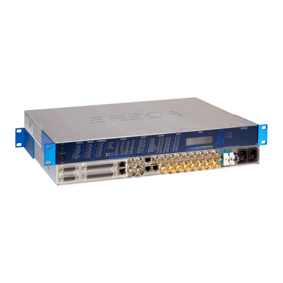
SR2 Installation Manual EN 4 / 19 1.2 CONNECTORS LOCATION The Stage Racer 2 provides signals, optical and power connectors on the rear panel. Optional Serial connectors and optional DC power are fitted on the visualization panel. • Rear connectors •... -
Page 5: Interfaces Description/ Ports Mode
Ground and power pins are available on the connector to ease interfacing with others machines e specially if a dry contact, open connector or ground closure supplies the information. The 12 volts output of the Stage Racer 2 is protected against external short circuit by an internal 100mA resettable fuse (polyswitch) common to the GPI and GPO sockets. -
Page 6: General Purpose Out
+ 12V 100 mA GND (0V) Each GPI can be affected to one or Multiple GPO by using the GPIO routing grid of the Stage racer 2. ERECA, 75 rue d'Orgemont, 95210 Saint Gratien, France T: +33 1 39 89 76 23... -
Page 7: Analog Audio
48Volts will still be present for few seconds on the inputs, time needed by the inputs capacitor to discharge thru the internal discharge resistor. Note: The Mic gain board can be fitted afterwards. ERECA, 75 rue d'Orgemont, 95210 Saint Gratien, France T: +33 1 39 89 76 23 W: ereca.fr... -
Page 8: Aes / Madi
Each AES port is internally equipped with a 2-4 wire converter connected to transmit a fully bidirectional path to any distant AES port of the Stage Racer 2 network. It appears in the AES audio grid of the network. This allow to interconnect talkback panels working in a bidirectional manner on one 75 Ohms coax. The ports still can be used without configuration to transport unidirectional signal, no setup needed for channel direction. -
Page 9: Serial Ports
To build a half-duplex RS485 transmission, just bridge “pin 3 with pin 4” and “pin 5 with pin 6”. For RS485, setup the corresponding Baud rate within the web server to enable the Stage Racer 2 to manage the output impedance at the right serial byte duration. -
Page 10: Ethernet Ports/ Mode
Stage Racer 2 via the G/L port. In a Stage Racer 2 network, the G/L port is direction switchable and work as fol lows: when the Genlock port direction is set to input on a particular unit, the direction of all the other Genlock ports of all units connected to the network will automatically be set to output. -
Page 11: Sdi Video Ports
11 / 19 1.3.11 SDI VIDEO ports Depending on the choice at the time of order, the Stage Racer 2 can be built with either 12 or 24 video channels. Please note it is not possible to upgrade from 12 to 24ch. - Page 12 Losses in some rare cases of very old fiber. REMARK: It is advised to source the QSFP+ at Ereca as factory validates it one by one for compliance with Stage Racer 2 standard. Also the warranty label will be broken.
-
Page 13: Visualisation
13 / 19 1.4 VISUALISATION The display face provides a comprehensive LED panel of the STAGE RACER 2. For ease of trouble shooting one LED is affected per transmitted signal. The 2 mains PSU fuses are also located on this side of the equipment for ease of replacement. (Model is 250Vac 2Amp time lag 5x20mm fuse). -
Page 14: Expansion
SR2 Installation Manual EN 14 / 19 1.4.3 Expansion The stage racer 2 offers 4x10GB Ethernet expansion channels via the MPO connector for remote production and future various other applications. As an example of what can be done: • ST2110: Green LED, ON when ST2110 mode is activated in the machine. -
Page 15: Audio
500ms displaying if there was a level > -10dBm on the past 500ms period providing a smooth display. 1.4.7 GPIO • GPIO 1-8, Green LED ON, when a GPI or GPO is activated on their respective input and output. ERECA, 75 rue d'Orgemont, 95210 Saint Gratien, France T: +33 1 39 89 76 23 W: ereca.fr... -
Page 16: Oled Display
- Then the validate button on the right side of the screen needs to be pressed within 5s, otherwise, the operation will cancel automatically. - After the operation is complete, it is recommended to reboot the unit. ERECA, 75 rue d'Orgemont, 95210 Saint Gratien, France T: +33 1 39 89 76 23 W: ereca.fr... -
Page 17: Optional Connectors
If impedance matching is needed a small SFR16 resistor could be added directly on the D SUB pins, together with the signal wire. Note 1: For RS 485 Telex/RTS talkback panels please ask ERECA for wiring tip. Note 2: As the differential inputs are unloaded internally a small crosstalk should happen on the adjacent channel only if it is unused and left floating. -
Page 18: Technical Specifications
OLED display for main parameters (IP add / Optical power) / 1 LED per signal / Technical alarms LED Setup: Web interface / 3 party automation protocols (Cerebrum, KSC Core, VSM….) Connection: 1 dedicated 10/100Mbs ethernet port ERECA, 75 rue d'Orgemont, 95210 Saint Gratien, France T: +33 1 39 89 76 23 W: ereca.fr... -
Page 19: Options
06/01/2020 SR2 Installation Manual EN 19 / 19 2.2 OPTIONS STAGE RACER 2 OPTIONAL MODULES (retrofit possible) OPTION - Analog Audio Mic preamp / 48V Input: 8 Microphone input gain blocks fitted on channels 9 of the 16. Mic input, Gain: Gain from 10 to 60dB (3dB steps) / Preamp Bypass, through internal Web Server.
Need help?
Do you have a question about the STAGE RACER 2 and is the answer not in the manual?
Questions and answers