Table of Contents
Advertisement
Quick Links
Chameleon CoaXPress Camera
Simulator Hardware Reference and
May 2014
International Distributors
Installation Guide
(Part-No. KY-Chameleon)
Sky Blue Microsystems GmbH
Geisenhausenerstr. 18
81379 Munich, Germany
+49 89 780 2970, info@skyblue.de
www.skyblue.de
In Great Britain:
Zerif Technologies Ltd.
Winnington House, 2 Woodberry Grove
Finchley, London N12 0DR
+44 115 855 7883, info@zerif.co.uk
www.zerif.co.uk
Advertisement
Table of Contents

Summary of Contents for SKY BLUE Kaya KY-Chameleon
- Page 1 Simulator Hardware Reference and Installation Guide (Part-No. KY-Chameleon) May 2014 International Distributors In Great Britain: Sky Blue Microsystems GmbH Zerif Technologies Ltd. Winnington House, 2 Woodberry Grove Geisenhausenerstr. 18 81379 Munich, Germany Finchley, London N12 0DR +49 89 780 2970, info@skyblue.de +44 115 855 7883, info@zerif.co.uk...
-
Page 2: Table Of Contents
Contents Figures and Tables ....................2 Introduction ......................3 Safety Precautions ..................3 Disclaimer ....................4 Key Features ......................6 Overview ..................... 6 Features ....................... 6 Product Applications ................... 7 Related documents and accessories ............. 8 System Description ....................9 System Block Diagram ................ -
Page 3: Figures And Tables
Figures and Tables Figures 1: C ........9 IGURE HAMELEON RESS IMULATOR SYSTEM BLOCK DIAGRAM 2: C ................10 IGURE HAMELEON BOARD EXTERNAL VIEW 3: PCB M ..................12 IGURE ECHANICAL IMENSIONS 4: C ..................14 IGURE RESS SYSTEM CONNECTION LED’... -
Page 4: Introduction
Introduction Safety Precautions With your Chameleon CoaXPress Camera Simulator board in hand, please take a minute to read carefully the precautions listed below in order to prevent unnecessary injuries to you or other personnel or cause damage to property. Before using the product, read these safety precautions carefully to assure correct use. -
Page 5: Disclaimer
Introduction electricity. Do not use or place the product in the following locations. ● Humid and dusty locations ● Airless locations such as closet or bookshelf ● Locations which receive oily smoke or steam ● Locations close to heating equipment ●... - Page 6 Introduction KAYA Instruments assumes no responsibility or liability for: - Erasure or corruption of data arising from use of this product. - Any consequences or other abnormalities arising from use of this product, or damage of this product not due to our responsibility or failure due to modification. Repair of this product is carried out by replacing it on a chargeable basis, not repairing the faulty devices.
-
Page 7: Key Features
Key Features Overview The Chameleon is the industry’s first Camera Simulator supporting CoaXPress standard. This simulator is capable of generating video streams and test patterns of up to 4 CoaXPress links in single, dual and quad modes. Each link supports standard CoaXPress bitrates up to 6.25 Gbps. -
Page 8: Product Applications
Key Features Flexible machine I/O: 8 TTL configurable I/Os 4 LVTTL configurable I/Os 4 LVDS inputs 4 LVDS outputs 4 opto - isolated outputs 4 opto - isolated inputs 4 quadrature rotary encoder simulators ... -
Page 9: Related Documents And Accessories
Key Features Related documents and accessories Documents: Chameleon Camera Simulator User Guide Chameleon App User Manual Chameleon API Reference Book CoaXPress standard 1.0 Accessories: CoaXPress cables (DIN to DIN) CoaXPress cables (DIN to BNC) Chameleon CoaXPress Camera Simulator User Guide... -
Page 10: System Description
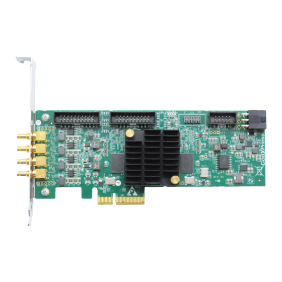
System Description System Block Diagram Figure 1: Chameleon CoaXPress simulator system block diagram External View of the Board Figure 2 shows the Chameleon Camera Simulator board specification. Chameleon CoaXPress Camera Simulator User Guide... -
Page 11: Figure 2: Chameleon Board External View
System Description Figure 2: Chameleon board external view Chameleon CoaXPress Camera Simulator User Guide... -
Page 12: Mechanical Specifications
Mechanical Specifications Essentials to get started To begin using your Chameleon Camera simulator, you must have a computer with the following: Processor with an Intel 64-bit architecture, or equivalent. An availably x4 (or x8 or x16) PCIe slot. Gen 2 support is recommended to faster data transfer. -
Page 13: Mechanical Dimensions
Mechanical Specifications Mechanical dimensions The Chameleon board is a Low profile PCIe card according to PCI Express Card Electromechanical Specification. This card can be installed in both Standard Height and Low profile computers, simply by replacing the bracket. The exact board mechanical dimensions are as defined in Figure 3. For more detailed information please, contact KAYA Instruments representative. -
Page 14: Installation And Configurations
Installation and Configurations Installation instructions Chameleon board is standard PCIe card with 4 lanes connector. It can be installed in any PCIe Gen2 connector of the motherboard with 4 lanes and up. Note: Board should be installed before you install your software. 1. -
Page 15: Chameleon Leds
Installation and Configurations Chameleon Simulator CoaXPress Frame Grabber Figure 4: CoaXPress system connection Chameleon LEDs Each CoaXPress link of the Camera Simulator equipment with indication bi-color LED. The LEDs behaves according to the defined in section 5.4 of the CXP standard. The possible LED’s states described in Table 2. -
Page 16: Chameleon Hardware Reference
Installation and Configurations LED 0 LED 1 LED 2 LED 3 CH 0 LED CH 1 LED CH 2 LED CH 3 LED Figure 5: Chameleon Board LED’s locations Board Status LEDs functionality is described in Table 3: LED # Description LED 0 Alive led. -
Page 17: Chameleon Board Block Diagram
Installation and Configurations Chameleon Board Block Diagram GPIO GPIO CoaXPress Video stream GPIO Controller channel 1.0/2.3 Driver Control channel Video stream CoaXPress 1.0/2.3 Driver channel Processing Control channel Unit CoaXPress Video stream channel 1.0/2.3 Driver Control channel CoaXPress Video stream 1.0/2.3 Driver channel... -
Page 18: Video Stream Generation
Installation and Configurations Video stream generation Chameleon is designed to generate different video streams compliant with CoaXPress standard 1.0 over 4 CoaXPress links. When connected to acquisition device, the board communicates with Frame Grabber device to determine link parameters, such as data rate. For different video generation options please refer to Chameleon Application User Manual. - Page 19 Installation and Configurations Figure 7: GPIO connectors location Chameleon CoaXPress Camera Simulator User Guide...
-
Page 20: Table 4: J7 Connector Pinout
Installation and Configurations The pinout of each of these connectors is as described in Table 4 and Table 5. Signal Name Function Electrical Standard Description Number IO_OUT_EXT0 Opto-Isolated Up to 70V Optically isolated output outputs IO_OUT_EXT0 Opto-Isolated Up to 70V Optically isolated output outputs... -
Page 21: Table 5: J9 Connector Pinout
Installation and Configurations Signal Name Function Electrical Standard Description Number IO_OUT_EXT0 Opto-Isolated Up to 70V Optically isolated output outputs IO_OUT_EXT0 Opto-Isolated Up to 70V Optically isolated output outputs IO_IN_EXT0 Opto-Isolated Up to 70V Optically isolated inputs input IO_IN_EXT0 Opto-Isolated Up to 70V Optically isolated inputs input RIN1p... -
Page 22: Table 6: Lvds Output
Installation and Configurations Electrical characteristics for board IO’s: Symbol Parameter Condition Units Differential Output Voltage ∆V Change in Magnitude of | mV | for Complementary = 100 Ω Output States Offset Voltage 1.12 1.23 1.375 ∆V Change in Magnitude of | mV | OUT- for Complementary... -
Page 23: Table 8: Lvttl
Installation and Configurations Symbol Parameter Test condition (note 1) Units ≥ V Input High Voltage +0.3 OH (min) ≤ V Input Low Voltage -0.3 OL (max) Input Current = 0 V or V ±5 µA Note: Vdd = 3.3V, unless specified otherwise Table 8: LVTTL input specifications Symbol Parameter... -
Page 24: Figure 7: Gpio
GPIO_5V_7 GPIO2 GPIO3 HEADER_2x10x100mil_SMT Figure 8: Opto-isolated IO’s schematic International Distributors In Great Britain: Sky Blue Microsystems GmbH Zerif Technologies Ltd. Geisenhausenerstr. 18 Winnington House, 2 Woodberry Grove 81379 Munich, Germany Finchley, London N12 0DR +49 89 780 2970, info@skyblue.de +44 115 855 7883, info@zerif.co.uk...
Need help?
Do you have a question about the Kaya KY-Chameleon and is the answer not in the manual?
Questions and answers