
Related Manuals for DLG Energy Soluna S8 EU-A50

Summary of Contents for DLG Energy Soluna S8 EU-A50
- Page 1 Installation Manual Battery Energy Storage System Soluna S8 EU-A50 DLG Energy (Shanghai) Co., Ltd. June 2020 Version V1.1 Page 1 of 60...
- Page 2 About this manual This manual describes how to install the SOLUNA Battery Energy Storage System (referred to as BESS from hereon), the Soluna S8 EU-A50, manufactured by DLG Energy (Shanghai) Co., Ltd. Please read this manual before you attempt to install the product, and follow the instructions throughout the installation process.
-
Page 3: Table Of Contents
Step 5 ..........................30 Step 6 ..........................31 Step 7 : .......................... 34 How to operate Soluna S8 EU-A50 ..................36 Turn on or turn off the Soluna S8 EU system ..............36 How to operate the LCD ....................37 The LCD is operated by touch, to view the information in the LCD simply touch to view the details.......................... -
Page 4: Safety Precautions
Safety precautions BESS are designed and tested following relevant international safety standards. As an electrical and electronic device, all applicable safety regulations must apply during installation, operation, and maintenance. Incorrect use or misuse may result • Injury to the life and personal safety of the operator or other people. •... -
Page 5: Warning Signs
Warning signs Warning signs are used to warn you about the conditions that may cause severe injury or damage to the device. They instruct you to exercise caution to prevent danger. The following table describes the warning signs used in this manual. Sign Name Description... -
Page 6: Safety Guide
Safety guide After receiving this product, first, confirm the product package is intact. If any question, contact the logistic company or local distributor immediately. The installation and operation of the system must be carried out by professional technicians. They have received professional training, and thoroughly familiar with all the contents in this manual and the safety requirements of the electrical system. -
Page 7: Transportation And Installation
Transportation and installation • Keep the package and unit complete, dry and clean during storage and transportation. • Please remove and install it with at least two people. • To ensure the safe operation of the BESS and avoid personal injury, please select proper handling and installation tools, and take mechanical protection measures to PPE, such as wearing steel toe capped shoes, overalls and so on. -
Page 8: Grid-Tied Operation
Grid-tied operation • Only qualified electricians are allowed to operate the system under Note the permission of local power departments. • All electrical connections must meet the electrical standards of the countries/regions where the installation is happening. • Ensure a reliable installation and electrical connection before operation. •... -
Page 9: Product Introduction
Product Introduction Soluna’s S8 EU-A50 can connect with a solar power generation system, assisting the customer to use environmentally-friendly energy 24 hours per day. The BESS can store the energy generated by the PV, using it when required, reducing electricity bills, improving the household energy self-consumption and working when there is a BLACKOUT. -
Page 10: Outline Dimensions
Outline Dimensions Figure 2.1 outline dimension Width Depth Height 1335 Weight Page 10 of 60... -
Page 11: Functional Description
Functional description The basic principle of Soluna S8 EU-A50 Figure2.2 basic principle of Soluna S8 EU Page 11 of 60... -
Page 12: Working Modes
Working modes Soluna’s S8 EU-A50 have the working modes (see below): Mode 1: In the daytime, the PV power will charge the battery as a priority, if the battery is full, the PV power is used to power the loads, then finally excess energy is sold to the Grid. -
Page 13: Always Check The As4777.2: 2015 Settings With The Local Grid Operator
Active power and reactive power setting The Soluna BESS is capable of producing reactive power and feeding it into grid through the setting. Feeding in management can be controlled directly by the grid company through a dedicated communication port. Volt-Var Response Mode The Soluna BESS series complies with AS/NZS 4777.2: 2015 standard which introduced the voltage-var response mode to restrict the power output of the inverter in response to the voltage at its terminals (refer to AS/NZS 4777.2: 2015). - Page 14 Volt-Watt Response Mode The Soluna BESS series complies with AS/NZS 4777.2: 2015 standard. The grid voltage at which the inverter output starts to drop/de-rate is set to 250 V by default as required by the standard. This means that when the grid voltage exceeds 250 V, the maximum output of the inverters will be restricted (as required by the standard).
- Page 15 Remark: User can find the QV & VM icon in reset & advanced setting icon on the LCD), Please find the following picture for details. DRMs, logic interface for AS/NZS 4777.2:2015, is used to receive and response commands from grid company and then adjust inverter output power. The Earth fault alarm Before the inverter starts to connect to the grid, the inverter will first detect the impedance of PV + to ground, and the impedance of PV- to ground.
-
Page 16: Technical Data
Technical Data Technical data of System PV input Max. recommended DC power (W) 6500 Max. DC voltage (V) 500V Isc PV (absolute Max.) (A) 16A/16A Number of MPPT trackers Strings per MPPT tracker Nominal DC operating voltage (V) Max. input current (A) 11A/11A MPPT voltage range (V)... -
Page 17: Technical Data Of Battery Module
Cycle life 6000 Regular parameters Protective class Class I Overvoltage category OVC II(PV) , OVCIII(AC main Grid) Dimension (mm) W*D*H=750*565*1335 Weight (kg) Display 7'' graphic LCD Communication WIFI, CAN Operating temperature range (°C) -10~+40 Storage stability range (°C) -20~+60 Relative humidity 0~95% Altitude (m) <2000... - Page 18 <3W (work), Power consumption <100mW (sleep) System Voltage System Current Monitoring parameters Cell Voltage Cell temperature Communication System Configuration Module parallel 1~4 Parallel Operating Conditions Installation Location Indoor Operating Temperature -10~45 ℃ Operating Temperature (Recommended) 15~30 ℃ Storage Temperature -20~60 ℃ Humidity 5%~95% Altitude...
-
Page 19: Appearance
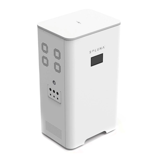
Appearance ① ② Figure 2.3 Appearance Number Name Remark ① Soluna brand ② LCD panel Page 19 of 60... - Page 20 Page 20 of 60...
- Page 21 Figure 2.5 Appearance Number Name Remark ① The door lock of the system ② The door key Page 21 of 60...
-
Page 22: Installation
Installation Installation tools Page 22 of 60... -
Page 23: Spacing During Installation And Subsequent Operation
Spacing during installation and subsequent operation Installation To ensure proper ventilation during installation, where possible, please reserve 200cms in all directions around the BESS. During operation Position Min spacing Remark Side spacing 100cm There needs to be a clearance of 100cm on either side of the Soluna BESS Back spacing... -
Page 24: Wiring Specifications
Wiring specifications To standardize the specification of AC and DC connectors or terminals of compatible inverters, the following requirements are required for connecting AC and DC wires of corresponding types of inverters PV side GRID side Load 4 mm² wire is recommended 6 mm² wire is recommended 6 mm² wire is recommended Installation step Unpacking confirmation Before unpacking, check carefully whether the product information in the order is... -
Page 25: Basic Installation Requirement
Basic installation requirement The BESS cabinet is IP20 and suitable for installation in dry, dusty environments. According to EMC standards, the BESS cabinet is designed to meet the installation requirements in a home environment. Select the installation site according to the following criteria: •... -
Page 26: Installation Procedures
Installation procedures The mechanical installation steps are as follows: Step 1 Remove the S8 EU-A50 casing and the battery modules from the packaging box Figure 3.1 battery module & system case Number Name Remark ① System case ② Battery modules Page 26 of 60... -
Page 27: Step 2
Step 2: The casing is attached to a wall: Figure 3. Attached the casing to the wall Number Name Remark ① Wall ② Soluna System ③ Expansion Screw ④ Fixed Bracket ⑤ Ground Page 27 of 60... -
Page 28: Step 3
Step 3 Open the door of Soluna system, and open the case of the battery module Figure 3.4 Battery Unit Number Name Remark ① System case ② Case of Battery module Page 28 of 60... -
Page 29: Step 4
Step 4: Push the battery module into the system, and lock the battery cable and plug in the CAN communication & Remote line. Figure 3.6 RJ45 terminal Number Name Remark ① Remote wire ② Battery cable ③ CAN communication line Remark: Connecting wire for communication line All CAN1 lines are parallel for the internal communication of battery units All CAN2 lines are parallel for external communications. -
Page 30: Step 5
Step 5 Fixed battery module and close the door of the BESS. Figure 3.7 Fixed battery module Number Name Remark ① M6*12 Combination screw ② Fixed bracket Page 30 of 60... -
Page 31: Step 6
Step 6 External circuit connection (PV\GRID\LOAD) Figure 3.8 External circuit connection Number Name Remark ① Emergency Stop ② Load connector ③ Grid connector ④ GEN connector ⑤ PV connector ⑥ GEN control port Page 31 of 60... - Page 32 Only qualified PV strings under the local electrical safety laws and regulations and comply with the technical parameters of this manual are allowed to connect to the Soluna S8 EU-A50. The PV string connected to the BESS must adopt the DC connector configured for the BESS. Do not use other connection devices without authorization from our company;...
- Page 33 Grid & Load connection Only qualified AC transmission cables under the local electrical safety laws and regulations and comply with the technical parameters of this manual are allowed to connect to the Soluna S 8 E U - A 5 0 Recommended wire specifications for safe system operation are as shown in the following table.
-
Page 34: Step 7
Step 7 : Electrical connection A. The following diagram is an example for the Australia, South Africa and New Zealand grid systems. Please see Figure A for details. Note: In Australia, the neutral cable of the On-Grid side and Back-Up side must be connected together, otherwise Back-Up function will not work. - Page 35 C. The following diagram is an example for off-grid system Note: After the inverter is installed and working as a Grid-connected BESS, please turn off the grid power to check if the back-up function is working to avoid potential problems for subsequent uses.
-
Page 36: How To Operate Soluna S8 Eu-A50
How to operate Soluna S8 EU-A50 Turn on or turn off the Soluna S8 EU system Turn on: Open the door, and turn on all the switch of Load/Grid/Battery/Remote. Turn off: Open the door, and turn off all the switch of Load/Grid/Battery/Remote. -
Page 37: How To Operate The Lcd
How to operate the LCD The LCD can be found on the front of the system (see image below). Figure 4.0 LCD Number Name Remark ① LCD panel Note: The LCD is operated by touch, to view the information in the LCD simply touch to view the details Page 37 of 60... -
Page 38: How To Check The Information On The Lcd Screen
How to check the information on the LCD screen The LCD screen includes 5 icons: 1. Status 2. Settings 3. Data 4. Production information 5. Battery capacity (in the middle) Figure 4.1 LCD Screen How to check the information of the PV/Load Power/Feed-in power/Battery power. The user can see the below interfaces after clicking the icon of status Figure 4.2 information of status icon... - Page 39 Figure 4.3 PV information Figure 4.4 Load information Figure 4.5 Grid information Page 39 of 60...
-
Page 40: How To Setting Parameters Of Soluna System
Figure 4.6 Battery information How to Setting parameters of Soluna system The user will find the following interface after clicking the icon of “Setting”. Figure 4.7 Setting icon information The user can find the following interface after clicking the icon of Power sources. Figure 4.8 Power source Page 40 of 60... - Page 41 Figure 4.9 Charging setting (1) Figure 4.10 Charging setting (2) Figure 4.11 Charging setting (3) Page 41 of 60...
- Page 42 The user can find the following interface after clicking the icon of power utilizations Figure 4.12 Discharging setting (1) Figure 4.13 Discharging setting (2) The user can find the following interface after clicking the icon of Languages Figure 4.14 Language selection Remark: There are 3 kinds of language option in the Soluna system English the default, French and German are also available.
- Page 43 The user can find the following interface after clicking the icon of timing Figure 4.15 Timing setting The user can find the following interface after clicking the icon of reset & advanced settings. The user needs to enter password if the user wants to restore the parameters of the S8 EU-A50.
-
Page 44: How To Check The Information Of "Data" Icon
How to check the information of “Data” icon. The user can find the following interface after clicking the icon of Data Figure 4.18 Data icon The user can find the following interface after clicking the icon of Solar generation Figure 4.19 Statistics solar generation The user can find the following interface after clicking the icon of “back to grid”... -
Page 45: How To Check The Production Information Of Soluna System
User can see the following interface after clicking the icon of “Equivalent tree planting”. Figure 4.21 Equivalent tree planting The user can find the following interface after clicking the icon of “save the earth”. Figure 4.22 Carbon dioxide emission reduction How to check the production information of Soluna system icon of “production information”. - Page 46 How to Check the fault information The user can find the fault information after click the fault icon Remark: The user will find an icon blinking in the upper right corner of the LCD panel if there is any fault during Soluna system operation Figure 4.26 Fault information Page 46 of 60...
-
Page 47: How To Maintain
How to maintain Fan maintenance The expected life of the BESS fan’ is 70000 hours under continuous working. The higher the ambient temperature, the shorter life of service of the fan. Check the fan every year to see the fan is working correctly; make sure there is air blowing out from the outlet of the system. - Page 48 LLC soft fault LLC overvoltage LLC over current PV1 voltage high PV1 voltage low PV2 voltage high PV2 voltage low PV1 over current PV2 over current Item Description Remark RTC error Eeprom error Inv soft fault Fan fault Cmd shut down Grid loss Load over current Battery over current...
-
Page 49: Remote Monitoring
Remote monitoring 1. Download APP iPhone: Search “Soluna” in Apple Store. Android: Search “Soluna” in Google play Store. Remark: Please see below picture for Soluna Icon Page 49 of 60... - Page 50 2. Register Click [Register] to create new account. you can use email to register. Page 50 of 60...
- Page 51 3. Create Plant 3.1 Click [+] and select [Create Plant]. Then scan the serial number of the stick logger, or manually enter the serial number. 3.2 Edit plant information. 1) Confirm your plant location (GPS function will automatically determine the plant site, if you want to modify the location, click the “map”...
- Page 52 3.3 Input Plant Name It is suggested to create a plant name like “location+name+capacity” (e.g. Soluna 8.1KW),then click [Done]. Page 52 of 60...
- Page 53 3.4 Now you can see your plant on the homepage Page 53 of 60...
- Page 54 4. Wi-Fi Connection Configuration Select the plant and click [Connect Again] in the tab [Device], select your device and click [Done] to the next step. Page 54 of 60...
- Page 55 Configuration (for Android user) 1) APP will automatically get your Wi-Fi network, so you need to enter your Wi-Fi password to continue the configuration, if the network is not accurate, select [switch network], then find or manually enter the network ID. Page 55 of 60...
- Page 56 2) The connection will automatically start after connect the network 3) It normally takes 3~5 minutes to configure successfully. Then, you can go back to tab [Device] and click [+Device] to add more devices. Page 56 of 60...
- Page 57 Configuration (for iOS user) APP will automatically get your Wi-Fi network, so you need to enter your Wi-Fi password to continue the configuration, if the network is not accurate, select [Switch network], then find or manually enter the network ID. Page 57 of 60...
- Page 58 2) Go to iPhone’s [Network Settings] interface, and select the stick logger’s network AP_XXXXX(S/N), Then return to Soluna APP, the stick logger will start to configure. Notice: If it is unable to find an AP_XXXXX(S/N) in wireless network list, please make sure to shorten the distance between Wi-Fi routers and stick Logger to under 10 meters, the connection or setting may appear problem, if you have repeat the above steps and Still cannot find the AP_XXXXX, please follow the logger Manual for troubleshooting...
- Page 59 3) It normally takes 3~5 minutes to configure successfully, then, you can go back to tab [+Device] and click [+Device] to add more devices If the configuration fails, the reasons may be; 1. Router password is wrong, please click [Retry] and check the password 2.
-
Page 60: Contact Us
Contact us If any questions, please contact us. DLG Energy (Shanghai) Co., Ltd Soluna Address: No.3492 Jinqian Road, Shanghai, China 201406 Tel: +86-21-57475835 Email: sales@solunabattery.com Web: www.solunabattery.com Page 60 of 60...
Need help?
Do you have a question about the Soluna S8 EU-A50 and is the answer not in the manual?
Questions and answers