
Summary of Contents for Baelz Automatic BA 7020
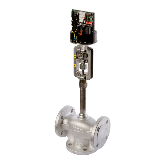
- Page 1 Page 1/24 Operating Instructions BA 7020 Baelz 7020 Digital Positioner in a Motorized Linear Actuator Technical specifications subject to change without notice Copyright according to ISO 16016...
-
Page 2: Table Of Contents
Page 2/24 Operating Instructions BA 7020 Inhaltsverzeichnis 1. SAFETY Intended use For the operator Personnel Before starting work During operation 1.5.1 Transport, installation and mounting 1.5.2 Service and maintenance Working environment 2. PRODUCT DESCRIPTION 2.1 Identification 2.2 Specifications Accessories and options Operating conditions 3. - Page 3 Page 3/24 Operating Instructions BA 7020 7. ERRORS Error after an initialisation run Error during initialisation or during normal positioner operation? Error during normal positioner operation 8. SPARE PARTS 9. DECOMMISSIONING AND DISPOSAL 10. WIRING DIAGRAMS BAELZ 7020 10.1 Wiring diagrams for operation in safety mode ANNEX A: INSTRUCTIONS FOR OPERATION USING MODBUS A1.
-
Page 4: Safety
Page 4/24 Operating Instructions BA 7020 1. SAFETY Carefully read these operating Instructions, especially the following safety precautions, prior to installation and operation. Caution Potentially hazardous situation which could result in minor injury. Caution Also indicates a risk which may cause material damage. -
Page 5: Personnel
Page 5/24 Operating Instructions BA 7020 1.3 Personnel Only qualified personnel may operate this positioner or work in its vicinity. Qualified personnel are individuals who are familiar with the set-up, installation, commissioning, operation and maintenance of the positioner and possess the required qualification for their activity. The required or prescribed qualifications include, amongst others: ● Training / instruction and the authorization to switch electric circuits and devices / systems on and off in accordance with EN 60204 (DIN VDE 0100 / 0113) and the technical safety standards. -
Page 6: Product Description
Page 6/24 Operating Instructions BA 7020 2. PRODUCT DESCRIPTION 2.1 Identification Each Baelz 7020 positioner has a name plate. This plate includes specifications regarding the operating conditions of the device and the manufacturer’s device and serial number. Digitaler Stellungsregler Digitaler Stellungsregle baelz 7020 baelz 7020 Ger. Nr. C 100000 Ger. Nr. C 100001 FD 112’+17 FD 112’+17... -
Page 7: Specifications
Page 7/24 Operating Instructions BA 7020 2.2 Specifications Supply voltage 230 VAC -15 % / +10 %, 50 / 60 Hz, Option: 115 VAC 50 / 60 Hz, 24 VAC 50 / 60 Hz Fuse internal 1,6 A/T (slow-blow) Power consumption approx. -
Page 8: Accessories And Options
Page 8/24 Operating Instructions BA 7020 2.3 Accessories and options ● Free parameterisation software (Modbus RTU) - Interface RS 485 required! ● For laptops with USB we recommend our interface convertor (Order N o. 5280-051). 2.4 Operating conditions Positioners and related actuators are suitable for installation in industrial plants and in waterworks and power plants with a low pollutant concentration. -
Page 9: Montage
Page 9/24 Operating Instructions BA 7020 4. MONTAGE 4.1 Installation If the unit is to be installed in a horizontal position, it should be installed such that the struts of the yoke are vertically aligned. A - B ... -
Page 10: Installation Of Controller
Page 10/24 Operating Instructions BA 7020 4.2 Installation of controller Baelz recommends buying the positioner ready installed. 4.3 Connection to electrical supply Risk of electric shock! Danger Use a safe electricity supply. Under no circumstances should dangerous voltage reach the equipment! Safety fuses and cut-off switches must be available on site to protect from short circuiting and for activation of the positioner. -
Page 11: Quick Start Guide
Page 11/24 Operating Instructions BA 7020 5. QUICK START GUIDE 1. Set DIP switches 2. Connect to supply (see chapter 5.1, below) 3. Start initialization run (DIP 12 0→1, see chapter 6.4) ↑ 4. Ready to go! 5.1 Switching on the Baelz 7020: Tip: Configure using DIP switches 1-4 and 7-10 before switching on. -
Page 12: Detailed Instructions
Page 12/24 Operating Instructions BA 7020 6. DETAILED INSTRUCTIONS 6.1 Functions in standard mode: These operation instructions concern the standard mode. The DIP switches are used to define the most commonly required configurations. In Modbus mode, the user can carry out additional advanced settings. The advanced settings are explained in a separate set of operating instructions: "Baelz 7020 Digital Positioner - Operating Instructions for Modbus Mode" In standard mode, the following functions are predefined: ● The setpoint actual value is supplied to both analogue outputs (both can be connected). -
Page 13: Operating The Postioner
Page 13/24 Operating Instructions BA 7020 6.2 Operating the postioner Fig. 5: N↔S switch Fig. 4: DIP switches switches between The ex-works setting of the DIP rormal and safety switches is position 0, as shown. mode. Switch Function Position 1 "ON"... -
Page 14: Details On Dip Switches
Page 14/24 Operating Instructions BA 7020 6.3 Details on DIP switches: DIP 1 and DIP 2: are interpreted together DIP 1: 0 = voltage → DIP 2: 0 = 0-10 V or 1 = 2-10 V. DIP 1: 1 = current → DIP 2: 0 = 0-20 mA or 1 = 4-20 mA. Either a voltage source can be connected to the U-terminal or a current source to the I-terminal. - Page 15 Page 15/24 Operating Instructions BA 7020 DIP 11: DIP switch 11 defines the mode of operation: 1 = Modbus mode, 0 = standard mode. Standard mode is used to apply predefined normal settings. DIP 12: Starts an initialisation run when switched from 0 to 1. If DIP 12 is left in position 1 when the 7020 positioner is switched on, an initialisation run will not be startet.
-
Page 16: Initialisation Run
Page 16/24 Operating Instructions BA 7020 Valve Actuator Desired DIP switch 10 Result at valve characteristic characteristic characteristic equal percentage Signal Signal Actuator quadratic characteristic can only be selected in Modbus mode. Signal Signal linear Signal Signal Actuator characteristic equal percentage can only be selected in Modbus mode. -
Page 17: Meaning Of Led Signals
Page 17/24 Operating Instructions BA 7020 6.5 Meaning of LED signals green LED red LED Fig. 10: LED signals Meaning signal signal green off Unit is switched off. red off green off Initialisation run in progress. red on green Unit is not initialized. Potentiometer in ideal position for initialisation run (between 7.5 and flashing 17.5%). -
Page 18: Connection Terminals - Labelling And Allocation
Page 18/24 Operating Instructions BA 7020 6.6 Connection terminals - labelling and allocation E5 E6 92 93 98 99 22 23 24 25 26 Normal and safety modes, see chapter 6.8 Fig. 12: Labelling of connection terminals See also "Wiring diagram", chapter 10... -
Page 19: Operational Modes And Operating Options
Page 19/24 Operating Instructions BA 7020 6.7 Operational modes and operating options 6.7.1 Standard operation using DIP switches The DIP switches can be used to carry out standard configurations and operations (see Fig.Fig. 6 page 13). When DIP switch 11 is set to 0, the 7020 is in the standard operational mode. In standard mode, all DIP switches are active and the functions of the Baelz 7020 can be individually adapted. -
Page 20: Errors
Page 20/24 Operating Instructions BA 7020 7. ERRORS 7.1 Error after an initialisation run Following a successful initialisation run, only the green LED is lit. If the red LED is flashing, this indicates an error following an unsuccessful initialisation run. The first error to occur during initialisation is shown. If the green LED is lit, the unit had already been initialized before the current initialisation run. If the green LED is flashing, the unit had not been successfully initialized previously. -
Page 21: Error During Normal Positioner Operation
Page 21/24 Operating Instructions BA 7020 7.3 Error during normal positioner operation The green LED is lit during normal positioner operation. A flashing red LED shows an error during normal positioner operation. For this, DIP switch 12 must be set to 0. The red LED shows errors during positioner operation as follows: ( = long flash, = short flash) Error code 1: interval interval etc. -
Page 22: Spare Parts
Page 22/24 Operating Instructions BA 7020 8. SPARE PARTS When ordering accessories or spare parts, please refer to the name plate on the positioner. The name plate gives the correct technical specifications and power supply requirements of the unit. Faulty or incorrect spare parts cause damage! Attention Spare parts must comply with the technical requirements supplied by the manufacturer. -
Page 23: Wiring Diagrams Baelz 7020
Page 23/24 Operating Instructions BA 7020 10. WIRING DIAGRAMS BAELZ 7020 AI2 0 = U / 1 = I AI2 0 = 0V/0mA 1 = 2V/4mA Lout AO1/2 0 = 0V/0mA 1 = 2V/4mA Actuator-spindle 0=0V=Out/1=0V=In Lo/DO1 DO3 Switch-point set = 0 >... -
Page 24: Wiring Diagrams For Operation In Safety Mode
Page 24/24 Operating Instructions BA 7020 10.1 Wiring diagrams for operation in safety mode Spindle extended = valve closed Spindle extended = valve closed Spindle extended = valve open Spindle extended = valve open excessive temp. (OT) has priority antifreeze (FP) has priority excessive temp. - Page 25 Page A1/9 Operating Instructions BA 7020 Baelz 7020 Digital Positioner Appendix A: Instructions for Operation using Modbus Technical specifications subject to change without notice Copyright according to ISO 16016...
-
Page 26: Annex A: Instructions For Operation Using Modbus
Page A2/9 Operating Instructions BA 7020 ANNEX A: INSTRUCTIONS FOR OPERATION USING MODBUS These instructions describe the extended operating options of the baelz 7020 positioner using Modbus VT100 in standard mode. Functions that are accessible and configurable in standard mode are described here. For the required accessories, see Chapter 2.3. A1. FUNCTIONAL DESCRIPTION The 7020 can be operated using Modbus VT100. -
Page 27: A2.2 Functions Of Keys In Winbas Tools A3
Page A3/9 Operating Instructions BA 7020 A2.2 Functions of keys in WinBas Tools The buttons in the display are operated by mouse click or with the corresponding keyboard keys. ● Return to main menu. Scroll quickly through menu items/values. Useful for changing ●... -
Page 28: A3. Load/Save Data A4
Page A4/9 Operating Instructions BA 7020 A3. LOAD/SAVE DATA WinBas Tools includes the function to "Load/Save Data". The "Load/Save Data" function allows a backup copy of the 7020 configurations to be created on the PC (DIP switch positions are excluded). The entire 7020 EEPROM content can thereby be saved in a file on the PC. The backup copy can be loaded from the PC back onto the same or another 7020 device. -
Page 29: A4. Menu Items
Page A5/9 Operating Instructions BA 7020 A4. MENU ITEMS A4.1 IMM menu Indication Main with Manual operation: Actual value, setpoint, statuses of digital outputs and inputs, manual/automatic operation. Abbreviation Written out Parameter/Function Explanation Manipulated Manipulated variable, 0%–100% or Variable actual value AI1... -
Page 30: A4.3 Menu Ii
Page A6/9 Operating Instructions BA 7020 A4.3 Menu II Indication Initialisation: Initialization State/Results Initialization Process Initialization Initialization Y = Yes (device is initialized) N = No (device is not initialized) I = Initializing (initialization in progress) Error Code Error code after... - Page 31 Page A7/9 Operating Instructions BA 7020 A4.6 AIP menu Actions: Initialization and Positions 2EZ: Action input: Initialization and positions 2EZ Start (Stop) Initialization Start/Stop Initialization Function like DIP switch 12: Process 1: Initialization in progress/start initialization process 0: Stop initialization process...
- Page 32 Page A8/9 Operating Instructions BA 7020 A4.8 CAO menu Configuration Analog Outputs: Configuration analog inputs. Not relevant in standard mode because the configuration of analog outputs is predefined. A4.9 CD menu Configuration Digital: Configuration of digital inputs and outputs Not relevant in standard mode because the configuration of digital inputs and outputs is predefined. A4.10 CA menu Configuration Alarms: Configuration of alarms Only menu items relevant to standard operation are outlined here. Abbreviation Written out...
-
Page 33: A4.11 Cm Menu A9
Page A9/9 Operating Instructions BA 7020 A4.11 CM menu Configuration Miscellaneous: Configuration miscellaneous Only menu items relevant to standard operation are outlined here. Abbreviation Written out Parameter/Function Explanation Password Password input in event The password input only appears when the that configuration level is configuration menus for inputs are disabled.
Need help?
Do you have a question about the BA 7020 and is the answer not in the manual?
Questions and answers