
Related Manuals for GDI COMMUNICATIONS FLD2SA Series

Summary of Contents for GDI COMMUNICATIONS FLD2SA Series
- Page 1 FLD2SA-1S FLD2SA-2S Manual Dual Port Fiber Optic Modem Standalone A00477-3 Rev. A For FLD2SA A00197-3 Rev. A and newer Serial numbers FLD-700084SA and up...
- Page 2 GDI Communications LLC. Recipient further agrees not to incorporate these drawings, specifications or technical information, in whole or in part, in any other product or endeavor.
-
Page 5: Table Of Contents
TABLE OF CONTENTS GLOSSARY ..............................1 GENERAL DESCRIPTION........................2 GENERAL CHARACTERISTICS ......................4 RJ45 T ........................4 ERMINATION ABLE DB9F T ........................4 ERMINATION ABLE INSTALLATION............................6 ........................6 ONFIGURATION WITCHES TYPICAL SYSTEM OPERATION......................10 : ......................11 YPICAL YSTEM CONNECTIONS ADJUSTMENTS ............................ -
Page 6: Glossary
Optical Port – A data communications GLOSSARY portal through which electrical data is transmuted to single frequency Anti-Streaming – A function on GDI coherent light waves and then modems that prevents a Host from transmitted through a fiber optic cable. transmitting continuously. -
Page 7: General Description
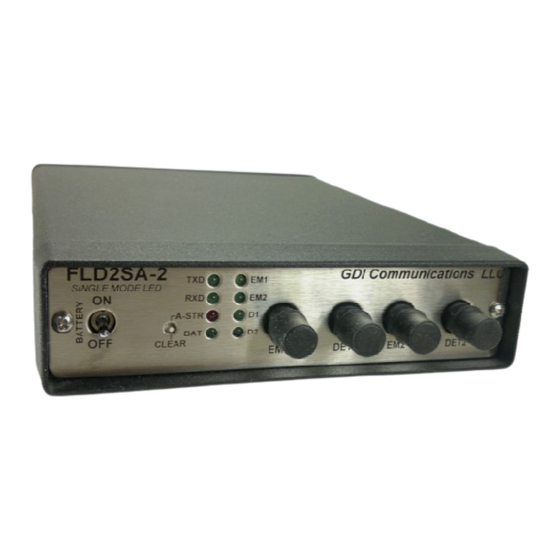
This allows the technician to see if a GENERAL DESCRIPTION controller ever had a problem and allows the controller to operate The FLD2SA has four fiber optic ports: normally if the problem clears itself. two emitters and two detectors. This allows a standard daisy chain The NiMH batteries are assembled in a configuration with two fiber optic... - Page 8 An expansion port (RJ45 connector) allows you to connect to another FLD2SA. This effectively puts two modems in parallel. If both modems are set to Master mode, four networks can be accessed. When connecting between two next generation FLD2SA units, no special cable is required.
-
Page 9: General Characteristics
General Characteristics RJ45 Termination Table PHYSICAL Function CASE….. 8.77” x 5.75” x 1.5” Weight………~2 lbs. SGND POWER: Voltage……….90-135 VAC 47-63 Hz Power…………..<5 Watts ENVIRONMENTAL: DB9F Termination Table TEMP:………..-37° ° ° ° to +74° ° ° ° C EIA-232 EIA-485 Function Function DCD* TXD+... - Page 10 PWR………………DC power is up FIBER OPTIC SECTION: Receiver Sensitivity: 850 nm Multi-Mode….……-40 dBm 1300 nm Single-Mode……..-33 dBm Transmitter Power: 850 nm Multi-Mode……….-15 dBm 1310 nm Single-Mode…..-21 dBm (std) CONNECTORS: 850 nm Multi-Mode…………ST 1300 nm Single-Mode LED….ST FC is opt. INDICATORS: TXD………..Transmit data from the Local or Master RXD……….Receive Data to the Local...
-
Page 11: Installation
INSTALLATION Switch 1: When set to “MASTER” mode, the Prior to installation, the FLD2SA must two fiber ports are in a parallel be configured to match the system arrangement. Both emitters are requirements driven with TXD data from the host. The data from both detectors drive While this can be performed with the RXD back to the hose. - Page 12 Switch 3 and Switch 4: Switch 3 turns ON, or OFF, the gating of CTS by the DET2 data. Normally, CTS is triggered by RTS and in a typical “Polling” application the FLD2SA will need no further data routing. However, for other applications, it may be necessary to turn CTS off when data is being transmitted from an upstream FLD2.
- Page 13 But, when switch 5 is in the “ON” position, CTS is held off until the upstream controller has finished transmitting and the DET2 data is no longer present. The time between when DET2 data stops and CTS is asserted is set by Switch 4.
- Page 14 Switch 5: The directionality of the Data and control signals on the Expansion port RJ45 can be set to DCE or DTE depending on the topology. A network can be expanded by connecting two FLDSAs together using a CAT5 patch cable. Set the downstream FLD2SA to DTE and the upstream FLD2SA to DCE.
-
Page 15: Typical System Operation
TYPICAL SYSTEM OPERATION REMOTE MODE The configuration switches are set from the factory to accommodate most When the FLD2SA is set for the Remote controller interface signals. Mode of operation, data coming downstream from the Master comes in However, in some cases, it may be Detector 1 and is sent to Emitter 2, necessary to adjust the polarity of the RXD, and the RJ45 connector. -
Page 16: Typical System Connections
Typical System connections: End Master: The master controller’s FLD2SA should be set to disable Detector 2. Notice that the end modem is also set to “Master” mode and its Detector 2 disabled. This is to completely isolate Center Master: fiber port 2. Notice that both end modems are set to “Master”... - Page 17 The following is an example of a extended network. The “Expansion port is used to link one FLD2SA to another FLD2’s expansion port.
- Page 18 This is an example of a “Expanded” By using the “C20” connector, the network using co sited FLD2SAs. expanded FLD2SA can operate in “Master” mode and drive both fiber The “Expansion port of the Master ports. This allows the master to drive FLD2SA is connected to the M14 four networks.
-
Page 19: Adjustments
ADJUSTMENTS The FLD2SA will not need any adjusting. The only changes that may be required are the configuration switches. This will have to be determined based on the controller operation. A factory test procedure with full instructions on how to test and setup the modem will be provided on request. - Page 20 This page is intentionally left blank...
- Page 21 GDI COMMUNICATIONS, LLC GDI FLD2SA-1S/FLD2SA-2S MANUAL A00477 Rev. A 879 Deming Way Sparks, NV 89431 TELEPHONE: 775-345-8000 FAX: 775-345-8010...
Need help?
Do you have a question about the FLD2SA Series and is the answer not in the manual?
Questions and answers