Table of Contents
Advertisement
Quick Links
Shoreline IoT
Shoreline IoT
Box Contents
1.
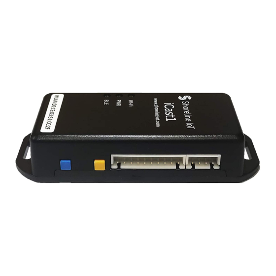
iCast1 Wireless IoT Bridge
2.
4-pin connector for 12-24V DC power
and RS-485 with 24-inch pigtail
3.
10-pin connector for digital I/O and
analog inputs with 24-inch pigtail
4.
12V, 600mA US plug power adapter
5.
DC plug terminal connector
6.
Reference card
What more you need to get started?
A 2.4 GHz Wi-Fi access point with active internet connection.
A Modbus RTU slave device or digital I/O or analog inputs to be monitored.
An iOS or Android device with Bluetooth (only used for initial device provisioning)
Setup the iCast1 unit
Connected to Wi-Fi & Cloud
Power is On
Connected to Bluetooth
Device Power: Connect 12V power adapter from the package to female DC plug using the 4-pin cable assembly
(Red –Positive, Black – Negative)
Note : Device can also be powered from MODBUS slave device with in-built power output (12-24 V, 10W). In this case,
the 12V power adapter provided with the package need not be used.
Connect MODBUS slave RTU, using the blue and white wires from the 4-pin cable assembly ( Blue: D+, White: D- ).
The external Modbus RTU device should share the same 0V supply reference as this device or should have an isolated
RS-485 communications port.
15750 Winchester Blvd Suite 206, Los Gatos, CA 95030 l www.shorelineiot.com l Shoreline IoT Confidential
iCast1 - Quick Start Guide
+5 V DC Output, 0.5 A
DI Reference (Input Range from 3.3 - 24 V)
4 Digital Pins Config
As Digital Input & As Digital Output
Analog Input #1 (0-10V OR 4-20mA )
Analog Input #2 (0-10V OR 4-20mA )
Reset Button
BLE Button
To Modbus
(D+)
Connection
(D-)
1 of 2
Advertisement
Table of Contents

Related Manuals for Shoreline IoT iCast1

Summary of Contents for Shoreline IoT iCast1
- Page 1 The external Modbus RTU device should share the same 0V supply reference as this device or should have an isolated RS-485 communications port. 15750 Winchester Blvd Suite 206, Los Gatos, CA 95030 l www.shorelineiot.com l Shoreline IoT Confidential 1 of 2...
- Page 2 For iCast1 to interact with connected sensors, the user needs to create a device profile describing the sensors' attributes. A device profile is the configuration which defines the sensors attached to iCast1 that needs to be monitored and logged. You can create a Device Profile from your account at https://cloud.shorelineiot.com, or you can use the default profile for now and create a profile after the new iCast1 device is connected to your account.
Need help?
Do you have a question about the iCast1 and is the answer not in the manual?
Questions and answers