Table of Contents
Advertisement
Quick Links
a division of Romac Industries, Inc.
OPERATING MANUAL
TAPMATE
XL 424
™
Pipe Drilling Machine
Thank you for your purchase of the TapMate
XL 424 Pipe Drilling Machine.
™
Please read and understand this operation manual. Our goal is to serve you, our customer.
If you have any questions, complaints or improvement suggestions please call us at 1‑800‑426‑9341.
06/19/2019
Advertisement
Table of Contents

Summary of Contents for Romac Transmate TapMate
- Page 1 Romac Industries, Inc. OPERATING MANUAL TAPMATE XL 424 ™ Pipe Drilling Machine Thank you for your purchase of the TapMate XL 424 Pipe Drilling Machine. ™ Please read and understand this operation manual. Our goal is to serve you, our customer.
-
Page 2: Table Of Contents
TAPMATE XL 424 OPERATING MANUAL ™ TABLE OF CONTENTS Specification ......................3 Machine Overview ....................4 ASSEMBLY Open the Shipping Crate ..................5 Cutter and Pilot Identification ................6 About Adapter Hub Sizes ..................7 Adapter Hub Installation and Removal ..............8 TapMate XL‑424 Set‑Up for 4"‑12" Taps ............. 10 TapMate XL‑424 Set‑Up for 14"‑24"... -
Page 3: Specification
TAPMATE XL 424 OPERATING MANUAL ™ TAPMATE™ XL-424 MACHINE SPECIFICATION • Heavy duty steel construction. • Hydraulic motor integrated to shaft and machine. • Weight of the TapMate XL‑424 is 285 lbs. (less the Adapter Bell, Pilot Drill and Cutters). •... -
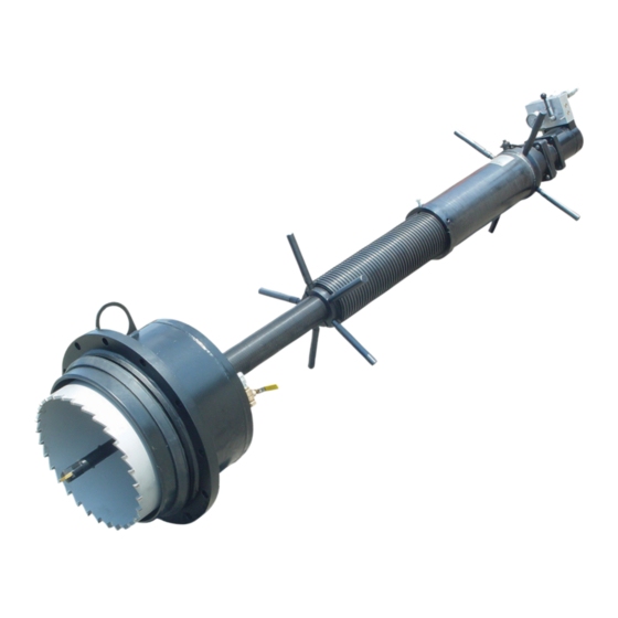
Page 4: Machine Overview
TAPMATE XL 424 OPERATING MANUAL ™ MACHINE OVERVIEW While you may be familiar with the TapMate drilling machine, the TapMate XL‑424 is larger and has different operating requirements. These include: • The TapMate XL‑424 has no sliding Tubes or Brakes. •... -
Page 5: Open The Shipping Crate
TAPMATE XL 424 OPERATING MANUAL ™ OPEN THE SHIPPING CRATE/WORKSTATION 1. Open all (six) of the latches around bottom of the Crate. 2. Swing open the End (see fig. 2). fig. 2 3. Lift and remove Cover (see fig. 3). fig. -
Page 6: Cutter And Pilot Identification
TAPMATE XL 424 OPERATING MANUAL ™ CUTTER AND PILOT IDENTIFICATION 1. Select the proper Cutter and Pilot for the pipe you'll be tapping (see fig. 4 & 5). Cutter and Pilots shown below are for use on Ductile Iron, Cast Iron and Asbestos/Cement pipe. -
Page 7: About Adapter Hub Sizes
TAPMATE XL 424 OPERATING MANUAL ™ ABOUT ADAPTER HUB SIZES 1. Ensure that the correct Adapter Hub is securely attached to the Lead Tube. To determine which Adapter Hub you'll need, see fig. 6 below. Small Adapter Hub Large Adapter Hub for use with for use with 4" ‑ 12" TapMate Adapter Bells. 14"... -
Page 8: Adapter Hub Installation And Removal
TAPMATE XL 424 OPERATING MANUAL ™ ADAPTER HUB INSTALLATION AND REMOVAL Installation: Large Adapter Keyway 1. Select the appropriate Adapter Hub for the size Lead Tube of Adapter Bell to be used (Small Adapter Hub Locking Collar for 4"‑12" and Large Adapter Hub for 14"‑24"). 2. - Page 9 TAPMATE XL 424 OPERATING MANUAL ™ ADAPTER HUB INSTALLATION AND REMOVAL (cont.) 4. Tighten with a Spanner Wrench. Small Adapter Hub Large Adapter Hub fig. 9 Removal: 1. Unscrew the Adapter Hub from the Lead Tube Locking Collar with the Spanner Wrench.
-
Page 10: Tapmate Xl-424 Set-Up For 4"-12" Taps
TAPMATE XL 424 OPERATING MANUAL ™ TAPMATE XL-424 SET-UP FOR 4"-12" TAPS: For instructions on attaching the Large Adapter Bell (for 14"-24" taps), turn to page 14. 1. After the Small Adapter Hub has been securely Small attached to the Lead Tube, check the neck of the Adapter Bell Adapter TapMate Adapter Bell to be sure that the O‑ring is... - Page 11 TAPMATE XL 424 OPERATING MANUAL ™ TAPMATE XL-424 SET-UP FOR 4"-12" TAPS (CONT.) 6. Thread the Brake Tube down the Thrust Tube by rotating it in a clockwise direction, as viewed from the back of the Machine (see fig. 14). Do this until the Shaft extends out of the Adapter Bell.
- Page 12 TAPMATE XL 424 OPERATING MANUAL ™ TAPMATE XL-424 SET-UP FOR 4"-12" TAPS (CONT.) 10. Thread the TM Shaft Nose or TM PVC Pilot (depending on the material of pipe you are tapping) into the end of the Shaft and tighten until the shank of the TM Shaft Nose or the TM PVC Pilot is flush against the face of the Shaft. Due to the longer body length of the 10 and 12 inch shell cutters, a Pilot Drill Extension must be at‑...
- Page 13 TAPMATE XL 424 OPERATING MANUAL ™ TAPMATE XL-424 SET-UP FOR 4"-12" TAPS (CONT.) 13. Remove the Front Workstation Brace from the Crate. fig. 20 14. The TapMate XL‑424 is now ready to be lifted and attached to the gate valve. When lifting the Machine, use the Lifting Rings at the Rear of the Machine and at the Small Adapter Hub as your lift points.
-
Page 14: Tapmate Xl-424 Set-Up For 14"-24" Taps
TAPMATE XL 424 OPERATING MANUAL ™ TAPMATE XL-424 SET-UP FOR 14"-24" TAPS For instructions on attaching the Small Adapter Bell (for 4"-12" taps), go to page 8. 1. Remove Front and Rear Braces from Work‑ station. 2. With the Large Adapter Hub properly in‑ stalled on the Lead Tube (see steps on page 8‑9), lift and move the appropriate size and style TapMate XL‑424 Adapter Bell into place... - Page 15 TAPMATE XL 424 OPERATING MANUAL ™ TAPMATE XL-424 SET-UP FOR 14"-24" TAPS (cont.) 7. Thread the Brake Tube down the Thrust Tube by rotating it in a clockwise direction, as viewed from the back of the Machine (see fig. 24). Do this until the Shaft extends out of the Adapter Bell.
- Page 16 TAPMATE XL 424 OPERATING MANUAL ™ TAPMATE XL-424 SET-UP FOR 14"-24" TAPS (cont.) 9. Take the TM XL‑Shaft Nose (or TM XL‑PVC TM XL Shaft Nose Pilot) and examine the Retention Pin System. It should require firm pressure to depress the Pin, and the Pin should snap back into place smoothly.
- Page 17 TAPMATE XL 424 OPERATING MANUAL ™ TAPMATE XL-424 SET-UP FOR 14"-24" TAPS (cont.) NOTE: Due to the weight of some Shell Cutters, use a suitable strap and lifting mechanism when lifting and installing the Shell Cutter. 11. Move the appropriate size Shell Cutter over the Shaft Nose (or PVC Pilot) and onto the front boss of the Large Shaft Head.
-
Page 18: Attaching The Tapmate Xl-424 To The Valve
™ ATTACHING THE TAPMATE XL-424 TO THE VALVE: The illustrations in this section depict a 6” size‑on‑size tap using a Romac FTS420 Fabricated Steel Tapping Sleeve, an MJ by Flange Gate Valve and the TapMate XL‑424 machine with an MJ Adapter Bell. - Page 19 TAPMATE XL 424 OPERATING MANUAL ™ ATTACHING THE TAPMATE XL-424 TO THE VALVE (cont.) 5. Carefully release the pressure in the Sleeve and Valve. OPEN the Valve Gate completely. Valve Gate 6. Measure the distance from the Valve Flange Valve Centerline of Flange the Waterway...
- Page 20 TAPMATE XL 424 OPERATING MANUAL ™ ATTACHING THE TAPMATE XL-424 TO THE VALVE (cont.) 8. Move the TapMate XL‑424 into position (see fig. 36) and bolt it to the Valve. Care needs to be taken to properly align the TapMate XL‑ 424 Machine to the Valve.
-
Page 21: Performing The Tap
TAPMATE XL 424 OPERATING MANUAL ™ PERFORMING THE TAP: 1. Slowly thread the Brake Tube forward on the Thrust Tube by rotating the Brake Tube Han‑ NOTE: Holes and Scale misaligned. dles in a clock‑wise direction. This slides the Shaft, Shaft Nose (or PVC Pilot) and Cutter, through the Valve and Neck of the Tapping Sleeve. - Page 22 TAPMATE XL 424 OPERATING MANUAL ™ PERFORMING THE TAP (cont.) 4. Check the distance that the Brake Tube has moved on the scale of the Thrust Tube. This is the distance that the Shaft Nose (or PVC Pilot) and Cutter has traveled. This travel distance, including the distance that the Shaft Nose (or PVC Pilot) extended out from the Adapter Bell (see Step 3 on page 18), should be approximately equal to the distance that was measured in Step 6 on page 19.
- Page 23 TAPMATE XL 424 OPERATING MANUAL ™ PERFORMING THE TAP (cont.) 6. Attach the Hoses from the power supply to Hyd. Pressure In. the Hydraulic Drive Unit (see fig. 39). Hyd. Pressure Out. fig. 39 7. Move the Lever on the Hydraulic Drive Unit fig.
- Page 24 TAPMATE XL 424 OPERATING MANUAL ™ PERFORMING THE TAP (cont.) 10. Start feeding the Cutter into the Pipe wall by slowly rotating the Lead Nut Handles; these should rotate without much force, typically two fingers to an open hand. The Cut‑ ter will travel about 3/16” for each revolution of the Lead Nut. DO NOT OVER‑FEED. Over‑feeding can result in stalling the motor and / or damage to the Cutter.
- Page 25 TAPMATE XL 424 OPERATING MANUAL ™ PERFORMING THE TAP (cont.) 18. Release the water pressure in the LIFTING CHAIN POSITIONS FOR 4" - 12" TAPS Adapter Bell by opening the Exhaust Valve on the back of the Adapter Bell (14‑24” adapters). Small Adapter Hub Rear Lifting Ring Lifting Ring...
-
Page 26: Disassembly And Removal Of The Coupon
TAPMATE XL 424 OPERATING MANUAL ™ DISASSEMBLY AND REMOVAL OF THE COUPON For 4"–12" Taps 1. With the Machine resting on the Work Station, remove the Lifting Chains. 2. Secure the Lead Tube into the Work Station with the Front Brace and the Wing Nuts provided. This will prevent the Machine from rotating in the next step and also when the Adapter Bell is unscrewed from it. -
Page 27: Care And Maintenance
To do this, remove the Set Screw located in the Back Plate of the Machine (where the square end of the Shaft extends out of the Machine). With the 1/8”‑27 NPTF Zirc Fitting in place, pump five (5) shots of Grease into the Back Bearings. *Note: Romac uses Fuchs Lubricants "FM 2", any equivalent food-grade grease conforming to NSF-H1 may be used. -
Page 28: Parts Identification Drawings Tapmate Xl-424 (Included Items)
TAPMATE XL 424 OPERATING MANUAL ™ TAPMATE™ XL-424 (366-00) Items included with Base Machine ITEM NUMBER DESCRIPTION 366‑00 Base Machine (see following page for parts list) 366‑61 TM‑XL, STORAGE‑WORK STATION CRATE 366‑43 TM‑XL, LARGE ADAPTER HUB 366‑42 TM‑XL, SMALL ADAPTER HUB 366‑10 TM‑XL, LARGE SHAFT HEAD ASSEMBLY 366‑11... -
Page 29: Tapmate Xl-424 (Base Machine)
TAPMATE XL 424 OPERATING MANUAL ™ TAPMATE™ XL-424 Base Machine only (366-00) ITEM NUMBER DESCRIPTION 366‑23 TM‑XL, LEAD TUBE 366‑22‑2A TM‑XL, BRONZE BUSHING COMPLETE 366‑57‑3 TM‑XL, POLY PAK, 2‑1/4 ID X 2‑3/4 OD X 3/16, #1870‑2250 366‑22‑2 TM‑XL, BRONZE BUSHING 366‑57‑2 TM‑XL, 2‑232 O‑RING, 2‑3/4 ID X 3 OD 366‑23‑54... -
Page 30: Adapter Bells (4" - 12")
TAPMATE XL 424 OPERATING MANUAL ™ TM, ADAPTER BELL 4 – 8 INCH 350-05-XXXX 350-05-1032 TM,MJ ADAPTER, 4 350-05-1048 TM,MJ ADAPTER, 6 350-05-1064 TM,MJ ADAPTER, 8 350-05-2032 TM,125# FLANGE ADAPTER, 4 350-05-2048 TM,125# FLANGE ADAPTER, 6 350-05-2064 TM,125# FLANGE ADAPTER, 8 350-05-571 TM,ADAPTER BELL O-RING, 3 350-05-512... -
Page 31: Adapter Bells (14" - 24")
TAPMATE XL 424 OPERATING MANUAL ™ TM-XL, ADAPTER BELL 366-05-XXXX 366-05-1112 TM-XL, 14 INCH MJ ADAPTER 366-05-1128 TM-XL, 16 INCH MJ ADAPTER 366-05-1144 TM-XL, 18 INCH MJ ADAPTER 366-05-1160 TM-XL, 20 INCH MJ ADAPTER 366-05-1192 TM-XL, 24 INCH MJ ADAPTER 366-05-2112 TM-XL, 14 INCH FLANGEADAPTER 366-05-2128 TM-XL, 16 INCH FLANGEADAPTER 366-05-2144 TM-XL, 18 INCH FLANGE... -
Page 32: Small Shaft Head Assembly
TAPMATE XL 424 OPERATING MANUAL ™ 366-11 TM-XL, SMALL SHAFT HEAD ASSEMBLY 1) 366-11-01 TM-XL, SMALL SHAFT HEAD 2) 366-09-01 TM-XL, SHAFT HEAD BOLT 3) 366-09-02 TM-XL, SHAFT HEAD KEY 4) 366-09-03 TM-XL, SHAFT HEAD KEY SCREW, SHCS 1/4-20 X 1-1/4, 366-10 TM-XL, LARGE SHAFT HEAD ASSEMBLY 1) 366-10-01 TM-XL, LARGE SHAFT HEAD... -
Page 33: Tm-Xl, Pvc Pilot
TAPMATE XL 424 OPERATING MANUAL ™ TM-XL,PVC PILOT, COMPLETE TM-XL,PVC PILOT,COMPLETE (14" - 16") (18" - 24") 366-39-2 366-39 QTY 2 QVIM,SHAFT NOSE RETAINING PIN SET SCREW 1) 360-22-03 QTY 2 QVIM,SHAFT NOSE RETAINING PIN SPRING 2) 360-22-04 QTY 2 3) 360-22-02 QVIM,SHAFT NOSE RETAINING PIN 350-04 TM, PVC PILOT... -
Page 34: Tm-Xl, Shaft Nose
TAPMATE XL 424 OPERATING MANUAL ™ TM-XL,SHAFT NOSE,COMPLETE TM-XL,SHAFT NOSE, COMPLETE (18" - 24") (14" - 16") 366-38 366-38-2 366-38 366-38-2 1) 360-22-03 QVIM,SHAFT NOSE RETAINING PIN SET SCREW QTY 3 QTY 2 2) 360-22-04 QVIM,SHAFT NOSE RETAINING PIN SPRING QTY 3 QTY 2 3) 360-22-02... -
Page 35: Hydraulic Motor Assembly
TAPMATE XL 424 OPERATING MANUAL ™ HYDRAULIC MOTOR ASSEMBLY (366-72-10) ITEM DESCRIPTION NUMBER 366‑72‑700 TM‑XL, HYD MOTOR, WT700930C8330AAAAB TM‑XL, HYD MOTOR/MANIFOLD O‑RING 366‑72‑07 TM‑XL, HYD HOLLOW HEX PLUG, 4 HP5ON 366‑72‑05 TM‑XL, HYD MOTOR FLOW CONTROL 366‑72‑06 TM‑XL, HYD PRESSURE GAUGE, 0‑3,000 PSI 366‑72‑04 TM‑XL, HYD MOTOR MANIFOLD 366‑72‑09...
Need help?
Do you have a question about the Transmate TapMate and is the answer not in the manual?
Questions and answers