
Summary of Contents for Pumpenstein CCM Basic 5 Series
- Page 1 Manual of the Chipley Custom Machine Series 5 Basic and the Series 6 Pump Markers V 1.4 www.pumpenstein.com...
-
Page 2: Table Of Contents
Table of Contents: Series 6 Marker Schematic a. Facing Left Page 3 b. Facing Right Page 3 Series 5 Basic Marker Schematic a. Facing Left Page 4 b. Facing Right Page 4 III. Liability Page 5 Safety and Handling Page 6 Quick Start Guide Page 7 A Brief Description…... -
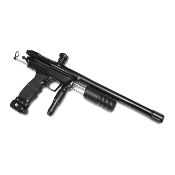
Page 3: Facing Left
The CCM® Series 6 (Facing Left) Control Bore Clamping Feed Neck Back Block 5/32 Allen Key Barrel Auto Trigger Timing Hole Allen Key Allen Bolt Pump Cocking Regulator Undertravel Screw Grip Frame 3/32 Allen Can also come in .45 style Regulator Adjustment 3/16 Allen Key... -
Page 4: Facing Left
IV. Series 5 Basic (Facing Left) Series 5 Basic (Facing Right) Note: All of the other parts are as named on the Series 6. Besides milling, the pump, and the detent – the Series 5 Basic is a very similar marker. -
Page 5: Liability
Pumpenstein or any of it’s members does not accept any liability for the handling of these markers, tools, air tanks, or any other item mentioned in this Unofficial manual. -
Page 6: Safety And Handling
VII. Safety and Handling: A Paintball Marker is not a toy. Any of the tools in this manual are not toys. Tools and paintball markers should be used only by adults or with adult supervision. Respect other peoples’ property and when using any paintball marker, obey all local, state and federal laws. -
Page 7: Quick Start Guide
VIII. Quick Start Guide: 1. Screw barrel onto marker – if your S5 B asic or S6 does not come with a barrel – use a barrel with Autococker® threads. 2. Place barrel blocking ‘Barrel Bag’ device properly onto the marker CAUTION: Always wear paintball approved eye and face protection when dealing with a pressurized paintball marker. -
Page 8: A Brief Description
IX. A Brief Description of the workings of the Series 5 and 6. A cutaway of a Series 5 Body with Sear Engaged This is the marker cocked with a ball in the chamber. When you pull the trigger a sear is lowered which releases a hammer (inside the bottom tube of the marker). - Page 9 Marker being pumped – hammer and bolt traveling to the rear – ball ready to drop in breach. The ball is temporarily held in place by the ball detents installed in your Series 6 marker (they are hidden under the little caps on the side of your marker that say S6).
- Page 10 every time the pump is returned to the starting position. With practice, the user can fire his Series 6 over six balls per second with accuracy. The auto-trigger is simply a cam that does not allow the trigger to fire until the pumping cycle is complete.
-
Page 11: Velocity
Velocity: CAUTION: Industry approved protective gear (for face and eyes) must be worn at all times while operating and performing adjustments on this marker. • Do not insert objects into the space between the cocking block and the main body of the marker at any point in time. Improper marker treatment may result in damage to the marker and serious injury to the operator. -
Page 12: Setting Up The Ccm Marker
XI. Setting up the CCM® Marker: If you have not played with your CCM® marker and have just pulled it out of the box – skip to #3 of this section. For those that have already been playing with their marker - start at #1. 1) Back out your regulator adjustment screw (3/16th) until the marker starts hissing down the barrel when you pull the trigger. - Page 13 However, a weaker main spring would lighten your pump stroke. I find the CCM® main spring is VERY light and I do not adjust my springs. I have found that 300 PSI is a great place to start with CCM® markers. You can use a Pressure Testing Gauge or just start low on the Regulator and turn it up from there.
-
Page 14: Additional Adjustments To The Ccm Marker
XII. Additional Adjustments to the CCM Marker: Sear / Lug: The lug height controls how far the trigger must be depressed in order to fire the marker. If this lug is set too high, the marker will not cock because the sear does not come into contact with the lug. - Page 15 Timing Hole – 1/8 Allen Turn the Allen key clockwise to lower the lug (allow the marker to fire with a longer trigger pull – or during auto trigger – later in the cycle) and to the anticlockwise to raise the lug (allow the marker to fire with a shorter trigger pull - or during auto trigger - earlier in the cycle).
- Page 16 Undertravel Screw: The undertravel screw (marked by the screwdriver in the picture below) is essentially only there to stop the Auto trigger and Cam from coming out of the grip frame. Pump the marker until you hear the sear ‘click’. Holding the pump in this position adjust the undertravel screw until it touches the trigger.
- Page 17 Pump Arm: Ensure that the bolt that attaches the Auto Trigger to the pump arm is perfectly perpendicular to the pump arm or else you will get binding and marring of the Auto Trigger arm. Cocking Rod: Set the cocking rod so that when you pump the marker the bolt just clears the chamber (looking down the feedneck) when the marker cocks.
-
Page 18: Regular Cleaning
XIII. Regular Cleaning. CAUTION: Always make sure you and everyone around you wears protection when you clean the marker or check it for paintballs. This is the cleaning I perform after every day of play. 1. Remove air source and ensure that all air has been released from the marker. 2. -
Page 19: Maintenance
XIV. Maintenance: From time to time, it may be necessary to clean or replace worn parts within the marker. For this, you will need to break down the marker further than the regular maintenance lists above. This section will be broken into subsections: The Grip Frame, the Chassis, and the regulator. - Page 20 2. Remove the grip screws (4 - 5/64 ) and the grip panels and the Frame Screws (2 1/8 Allen Screws for the Series 5 Basic and 2 - 3/32 for the Series 6) that attach the frame to the marker chassis. The screws on the Series 6 are submerged and thus can be simply loosened a turn or two and the frame slid to the rear of the marker and removed.
- Page 21 The Sear, Sear Pin, and Spring will come out. Inspect the Sear to see if it has wear where the lug catches. (Notice the slight wear on this sear.) Wear can cause the marker to ‘skip’ (not recock from time to time) or be VERY hard to time the auto trigger.
-
Page 22: Chassis Disassembly And Maintenance
Remove the Trigger Shoulder Bolt and slide the trigger from the frame (shown with the top Allen key). Also remove the Trigger Undertravel Screw (shown with the bottom Allen key) - it must be removed from the top of the frame. Use Blue Loctite®... - Page 23 4. Use 3/16th Allen Key (Series 5 Basic) or a Spanner to remove the Pump Rod. On the Series 5 Basic the Pump Arm Guide Ring will come with it. 5. Inspect the o-rings on the Series 5 Basic’s Guide Ring or the Series 6 Guide Rod.
- Page 24 This is the Series 5 Basic’s VRA. The S6’s has a small guide rod attached. 7. The VRA has one static o-ring – which I lightly lubricate upon reassembly. 8. Note the depth of the Lug before disassembly. You want to replicate this depth upon reassembly.
- Page 25 10. Insert a 1/8 Allen key into the Timing Hole (on the top of the marker) and turn the lug until it is flush with the hammer. This allows for the removal of the hammer. 11. Remove the Valve Retaining Screw and the Valve Retaining Nut Set Screw from the bottom of the marker.
- Page 26 Cutaway view showing removal of Valve Retaining Nut Screw. Cutaway view showing removal Valve Retaining Nut Set Screw. 12. Insert an Autococker® Valve Tool into the rear of the bottom tube until you feel it seat deeply on the Valve Retaining Nut and remove it. Because CCM®...
- Page 27 Cutaway showing Valve Wrench fully engaged in Valve Retaining Nut. Cutaway showing Valve Wrench removing Valve Retaining Nut. 13. Carefully dump out the Valve, Valve Seal, and Valve Spring.
- Page 28 This is the CCM® internals set. From left to right – top to bottom: IVG, Main Spring, Hammer and Lug, Valve Alignment Nut, Valve Body and Valve Body O-Ring, Valve Pin and Cup Seal, Valve Spring. 14. Inspect the Valve Seal. If it appears damaged – replace it. These can last a very long time, but dirt and other debris can cause them to fail.
-
Page 29: Regulator Disassembly And Maintenance
16. Clean these parts completely and reassemble. NOTE: When reassembling the Valve Assembly – stack the Valve Spring, Valve, and Valve body, and Valve Retaining Nut on top of the Autococker® Valve Tool and slide the body over this assembly. Be sure not to cross thread the Valve Retaining Nut into the Chassis of the marker upon reassembly. - Page 30 Disassembled Regulator (From Right: to Left: 3/16 Adjustment Screw, Regulator Housing Bottom, Regulator Spring Seat, Spring, Regulator Piston and O-Ring, Poppet Nut, Poppet Seat, Poppet Pin, Poppet Spring, Regulator Housing Top, O-Ring.) 1. Unscrew the halves of the regulator. CCM® has machined flats into the bottom of the regulator to assist in disassembly however, this is often not necessary to use.
- Page 31 4. Clean (use your Q-tips® in all the appropriate places on the regulator top) and replace the regulator Pin O-Ring if necessary. Apply a light coat of oil to these parts and replace them. 5. Use your Needle nose pliers to pull out the Regulator Piston and O-ring (marring the cone portion of the regulator piston is okay - just do not mar where the regulator pin touches the regulator piston).
- Page 32 8. Clean the bottom portion and replace the Regulator piston or Regulator Piston O-Ring if necessary. 9. CCM® packs the lower portion in clear grease. I have found no grease is necessary here and simply apply a coat of Dow® 55 or Hater Sauce on the Piston and Piston O-Ring.
-
Page 33: Pimpin' Your 'Ride
XV. Pimpin’ Your ‘Ride’: There is very little one can do to either of these markers to improve their performance. Both come with delrin bolts, polished and lightly sprung internals, and a good pump kit. However, I have experimented with trying to squeeze a little more performance out of both since I have owned them. -
Page 34: What To Do
during high rates of fire. I currently use a modified Sportshot Hopper that feeds great at about 6 to 7 bps that I can achieve in rapid fire. I find that an agitating loader simply adds weight and is unnecessary. Drop Forward: This may be a matter of opinion on my part but I think that due to the risk of the bolt smacking you in the mask when you re-cock the marker a straight rail... -
Page 35: Troubleshooting
XVI. Troubleshooting: My velocity is very erratic. This is most often caused by inconsistent paint sizing. See if your paint fits your barrel well and consistently. If not, try better paint. I have good paint and my velocity is still erratic. Clean your regulator. - Page 36 Marker leaks down the barrel after I pull the trigger but stops once I cock it again. This is most likely caused by your Regulator Pressure being too low. Follow the set up instructions above and this should solve this problem, or set the regulator at 300 PSI and it should stop this leak.
- Page 37 break very easily – this is most likely your culprit. Get a more robust shelled paint. Another common cause is that your detents are bad and you are double feeding paint. Again, you are not chopping paint but causing one ball to hit the other and break in the barrel.
-
Page 38: Series 6 Parts List
XVII. Series 6 – Parts List Item Material Vendor Part # Body Assembly: Body 6061 Aluminum DPM Back Block 6061 Aluminum DPM Body ‐ Upper Tube from the barrel: Bolt Tip Delrin DPM 2011 Aluminum Bolt Back or Delrin DPM Bolt Half Connecting Pin Steel McMaster 1/8 x 3/4 Roll Pin ... - Page 39 Small Guide Rod Stainless Steel DPM OD .190, Length 3.10 Pump Arm ‐ Drilled and Tapped Stainless Steel DPM Pump Kit Chassis 2011 Aluminum DPM Pump Guide Screw 2011 Aluminum Pump Kit Guide Screw O‐Rings Buna‐N McMaster N70‐015 Grip Frame from the Trigger Guard. 86 Degree or .45 Hinge Frame 6061 Aluminum DPM Trigger Delrin DPM Trigger Bearing H .250, W .110 Trigger Bearing Pin Steel ...
- Page 40 Regulator Lower Housing 2011 Aluminum McMaster Lower Housing top O‐ring Buna‐N McMaster N70‐017 Regulator Piston Delrin DPM Regulator Piston O‐ring Buna‐N McMaster N70‐113 Regulator Main Spring Music Wire Lee Springs Special Grind Regulator Spring Seat 2011 Aluminum DPM Regulator Adjustment Screw Stainless Steel McMaster 3/8 ‐ 24 x 5/8 18‐8SS Feedneck: Feedneck 2011 Aluminum DPM 7/8 x 20 Clamp Ring 2011 Aluminum DPM Clamp Ring Screw ...
-
Page 41: Contact Information For Ccm
Phone- 530-378-3420 Sales- 1-877-412-6850 Fax- 530-378-3420 www.chipleymachine.com XIX. Additions and Changes: We will be making changes to this manual periodically as we find out more and add more information. Please feel free to contact TF@Pumpenstein.com with any additions, corrections, or changes.
Need help?
Do you have a question about the CCM Basic 5 Series and is the answer not in the manual?
Questions and answers