Table of Contents
Advertisement
Quick Links
Advertisement
Table of Contents

Summary of Contents for Overkill Solar BMS Series
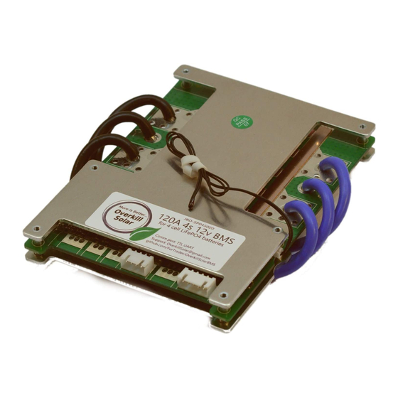
- Page 1 Overkill Solar BMS Instruction Manual Version: 0.1.0 Date: August 31, 2020 ...
-
Page 2: Table Of Contents
Table of Contents Table of Contents 2 1. Introduction 1.1 What is a BMS 2. How to Build a Battery Pack 2.1 Safety Precautions 5 2.2 Planning 2.2.1 Gather Components 5 2.2.2 Gather Consumables 6 2.2.2 Gather Tools 7 2.3 Top Balancing 2.4 Assembly 2.4.1 Arranging the Cells 2.4.2 Connect the Balance Wires... - Page 3 3.2.6 80%, 60%, 40%, 20% Capacity Voltage Levels 19 3.3 Balance Parameters 3.3.1 Start Voltage 20 3.3.2 Delta to balance 20 3.3.3 Balancer Enabled 20 3.3.4 Balance only when Charging 20 3.4 Other Parameters / Features 3.4.1 Switch 20 3.4.2 Load Detect 20 ...
- Page 4 12V BMS connector: 47 24V BMS connector: 47 D.1.2 BMS Serial Interface Connector 48 D.1.3 BMS Switch Connector 49 D.1.4 BMS Temp Sensor Connector 50 Appendix E: BMS Application Usage E.1. XiaoxiangBMS (iPhone) E.2. Xiaoxiang (Android) 51 E.3. JBDTools (PC) 54 ...
-
Page 5: Introduction
. The easiest approach is to purchase properly-sized bus bars with your battery cells (Overkill Solar’s 100 Ah LiFePO4 cells include bus bars). If you purchased other batteries that did not come with bus bars, they may be made ... -
Page 6: Gather Consumables
● An e nclosure for your battery pack. Popular choices are: ○ Overkill Solar sells a stainless steel frame for the 100Ah LiFePO4 batteries. This is arguably the strongest and most durable way to build a battery pack, and would be suitable for mobile ... -
Page 7: Gather Tools
● Wire shears , Klein Tools 63050 or similar ( needed to cut the large-gauge cables) ● Socket and wrench set ( needed to tighten the battery lugs). T he recommended Overkill Solar 100Ah LiFePO4 cells come with 17mm nylon-insert locking nuts. ... - Page 8 take five hours per cell. Do not leave the cells unattended during the balancing process. Plan your day accordingly. 1. Obtain a lab CC/CV (constant-current, constant-voltage) regulated power supply capable of providing at least 10 amps. 2. If you already jumped ahead and wired your battery pack up, disconnect everything now (remove the BMS, the bus bars, temp sensor, double-sided tape, everything. ...
-
Page 9: Assembly
2.4 Assembly 2.4.1 Arranging the Cells Lay out your cells in the correct orientation. Do not install the bus bars yet. NOTE: In this section, the 12V 4-cell and 24V 8-cell configurations are shown. Other configurations are covered in A ppendix A... - Page 10 Figure 2.4.1.1 : 12V 4-cell battery configuration, top-down view Figure 2.4.1.2 : 24V 8-cell battery configuration, top-down view Use a felt-tip pen (or a label maker) to label each cell, and each terminal on the battery. This will reduce the risk of making mistakes when connecting and reconnecting things.
-
Page 11: Connect The Balance Wires
using the optional steel frame, mount the cells in it now. If using a fully-enclosed box, it is recommended to get the components wired together and working first, and mount it inside the enclosure last. Add the bus bars, but don’t add the nuts or fasteners yet (balance leads go on before the nuts). ... -
Page 12: Prepare Bms
Figure 2.4.2.2: Balance lead connector and pinout, for 24V BMS Spin the nuts on as you go. Suggest torque is 20 ft-lbs (27 Nm), or “Nice and snug.” Warning: Do not pinch the balance wires under a nut! Instant smoke! 2.4.3 Prepare BMS ... -
Page 13: Temperature Sensor
2.4.5 Temperature Sensor The temperature sensor serves one purpose, and that’s to prolong the life of your battery cells when the temperature is too high or too low. Recall that lithium batteries do not work well at temperature extremes. This BMS is capable of protecting the battery cells in four different scenarios (each have their own trigger and ... -
Page 14: Connectivity
Figure 2.4.6.1 , diagram of a switch wired to the pigtail lead Any switch will do here, as long as it’s not momentary. Toggle switches or rocker switches are recommended. When soldering your switch to the lead, use heat-shrink tubing over the connections. ... -
Page 15: Usb Interface
Windows JBDTools_V1.B-20180820.zip Windows, Mac, Anticipated to be released by end TBD Overkill Solar Linux, Raspberry Pi of Q4 2020 Before plugging in the USB interface, install the applicable software (see table above). Do not run the software just yet. ... -
Page 16: Arduino Lcd Display
Then plug the other end of the USB cable to the computer. At this point, the computer should detect and recognize the device as a virtual serial COM port. The application may now be started. Instructions for using the application are covered in A ppendix E... -
Page 17: Cell Under Voltage
3.1.2 Cell under voltage Cuts off discharging current if any cell voltage goes under the Trigger value. Reconnects when all cells rise above the Release value. 3.1.3 Battery over voltage Cuts off charging current if entire pack goes over the Trigger value. Reconnects when pack drops below the Release value. ... -
Page 18: Battery Under Voltage
3.1.4 Battery under voltage Cuts off discharging current if entire pack falls under the Trigger value. Reconnects when pack rises above the Release value. 3.1.5 Charge over current Cuts off charging current if the current exceeds the trigger value, for [delay] seconds. Reconnects after [release value] seconds. ... -
Page 19: Discharge Over Current
3.1.6 Discharge over current Cuts off discharging current if the current exceeds the trigger value, for [delay] seconds. Reconnects after [release value] seconds. 3.1.7 Charge over temperature Cuts off charging current if the probe temperature exceeds the trigger value. Reconnects after the temp drops below the release value. ... -
Page 20: Designed Capacity
3.2.1 Designed Capacity This should be set to the battery pack’s capacity, in amp hours (Ah). It is not used to calculate the state of charge. It’s simply used when displaying the intended capacity of the cells. The actual capacity of the pack is defined as the ... -
Page 21: 80%, 60%, 40%, 20% Capacity Voltage Levels
3.2.6 80%, 60%, 40%, 20% Capacity Voltage Levels This should be set to the cell’s voltage at each of the four indicated state of charge levels. This information typically comes from the battery cell’s datasheet, which may may involve interpreting the discharge curve graph. -
Page 22: Led Enabled
3.4.3 LED Enabled Not applicable. Our BMS does not have the LED populated. 3.4.4 LED Capacity Not applicable. Our BMS does not have the LED populated. On BMS modules that have an LED, this would blink the capacity out (e.g., 5 blinks would mean 100% capacity). ... -
Page 23: Periodic Maintenance
4. Periodic Maintenance 4.1 Periodic Cable Check Periodically perform a cable check: 1. Ensure that the cables have not loosened. Use a wrench or socket to tighten any connections or terminals that have come loose. 2. Ensure that no wires have pinched or frayed; especially the balance wires. 4.2. -
Page 24: Troubleshooting & Faq
Besides permitting access, the location services may also need to be enabled. Note that after enabling location services, the GPS can be switched off. Please be aware that this is a Google Android phone quirk. The BMS does not require this information to work; nor does Overkill Solar care what ... - Page 25 your location is. Google’s excuse is that they are no longer using MAC addresses as identifiers between devices, and that they now use GPS. Which is probably BS. It’s probably an excuse to collect more location info which they store in their giant database. But there’s not much that can be done about it. ...
- Page 26 in discharge protection mode. If you don’t have access to shore power, then use either the second or the third method below. The second method is to “jump-start” the battery pack with another battery, which can be a lead-acid car or deep-cycle battery (if you’ve got a large-capacity lithium battery laying around, that would work too, but lead ...
- Page 27 Q: Someone told me that you don’t need a BMS. A: B elow on the left is a picture from one of our customers that wasn’t using a BMS. It was over-charged, which creates gasses, and can cause the outer case to bulge (this kills the battery). One of the jobs of a BMS is to prevent overcharging.
-
Page 28: Technical Support, Return, And Refund Policy
6. Technical Support, Return, and Refund Policy Email O verkillSolar@gmail.com for technical support. Our BMS policy is quite simple: If you need help, I will help. If it isn’t working right I will replace it. If it’s totally fried I will refund your money. This includes anything you did to break it. ... -
Page 29: Appendix
Appendix Appendix A: Recommended Parameters Recommended parameters for specific battery types are given in A ppendix B . General settings are listed below. A.1 General Settings Recommended generic settings can be found below. These settings assume LiFePO4 batteries. They can be used as a starting point. ... - Page 30 ● Balancer delta-to-balance: 15 mV ● Balancer enabled: True ● Balance only when charging: True Other Parameters / Features: These settings are consistent across all battery types. For capacity and protection settings, see the individual sections below for your specific battery type. ●...
-
Page 31: A.2: 12V Pack, 4 Cell, Using One 12V Bms And 100Ah Lifepo4 Cells
A.2: 12V Pack, 4 Cell, Using One 12V BMS and 100Ah LiFEPO4 cells Mechanical Drawing Figure A.2.1: 12V 4-cell pack assembly Bill of Materials # Qty Description Notes 1 1 12V BMS JBD-SP04S020 ... - Page 32 6 4 Battery cells 100Ah LiFEPO4 10mm, nylon locking. 7 8 Battery cell nuts for lugs Included with Overkill Solar LiFEPO4 cells Included with Overkill Solar 8 3 Bus bars LiFEPO4 cells 2 or more 3/8” lugs, red. 9 ...
-
Page 33: Wiring Diagram
Wiring Diagram Figure A.2.2: Wiring Diagram for 12V pack, 4-cell using one 12V BMS BMS Configuration Parameters Capacity configuration: Parameter Value Units 100000 Designed capacity mAh (100 amp hours) Cycle capacity 80000 mAh Full charge voltage (per cell) 3500 mV ... - Page 34 (seconds) Cell over voltage 3650 mV 3500 mV 2 Cell under voltage 2500 mV 3000 mV 2 Battery over voltage 14600 mV 14000 mV 2 Battery under voltage 10000 mV 12000 mV 2 Charge over current 130000 mA 32s 10 Discharge over current ...
-
Page 35: A.3: 12V Pack, 8 Cell, Using One 12V Bms
A.3: 12V Pack, 8 Cell, Using One 12V BMS Mechanical Drawing Figure A.3.1: 1 2V 8-cell pack assembly ... - Page 36 Bill of Materials Wiring Diagram Figure A.3.2: Wiring Diagram for 12V pack, 8-cell using one 12V BMS BMS Configuration Parameters Capacity configuration: Parameter Value Units 200000 Designed capacity mAh (200 amp hours) Cycle capacity 160000 mAh Full charge voltage (per cell) 3500 ...
- Page 37 20% capacity voltage (per cell) 3100 mV Protection parameters: Delay Parameter Trigger Value Release Value (seconds) Cell over voltage 3650 mV 3500 mV 2 Cell under voltage 2500 mV 3000 mV 2 Battery over voltage 14600 mV 14000 mV 2 ...
-
Page 38: A.4: 24V Pack, 8 Cell, Using One 24V Bms
A.4: 24V Pack, 8 Cell, Using One 24V BMS Mechanical Drawing Figure A.4.1: 24V 8-cell pack assembly Bill of Materials # Qty Description Notes 1 1 24V BMS JBD-SP10S009 ... - Page 39 6 8 Battery cells 100Ah LiFEPO4 10mm, nylon locking. 7 16 Battery cell nuts for lugs Included with Overkill Solar LiFEPO4 cells Included with Overkill Solar 8 7 Bus bars LiFEPO4 cells 2 or more 3/8” lugs, red. 9 ...
- Page 40 Wiring Diagram Figure A.4.2: Wiring Diagram for 24V pack, 4-cell using one 12V BMS BMS Configuration Parameters Capacity configuration: Parameter Value Units This should be the rated capacity of your battery in milliamps (multiply the amp-hours of your pack by 1000) ...
- Page 41 280 Ah pack: 224000 Full charge voltage (per cell) 3500 mV End of discharge voltage (per cell) 2800 mV Discharge rate 0.2 % 80% capacity voltage (per cell) 3400 mV 60% capacity voltage (per cell) 3300 mV 40% capacity voltage (per cell) 3200 ...
-
Page 42: A.5: 24V Pack, 8 Cell, Using Two 12V Bmss
Mechanical Drawing Bill of Materials Wiring Diagram BMS Configuration Parameters A.6: 48V Pack, 16 Cell, Using Two 24V BMSs TBD Mechanical Drawing Bill of Materials Wiring Diagram BMS Configuration Parameters ... -
Page 43: Appendix B: Calibration
Appendix B: Calibration Your BMS should come calibrated. In certain use-cases, the voltages and currents might be off. In most cases, calibration can fix this. We do not recommend doing this unless your readings are w ay off. It’s possible to damage your BMS or your battery bank if this process is not followed to the letter. ... -
Page 44: Current Calibration
B.2 Current Calibration You will need an accurate current meter to perform current calibration, and it must be able to measure the maximum current that the BMS is capable of withstanding. Most handheld meters will only measure up to 10 amps;... -
Page 45: Charge Current Calibration
Click the “Idle Calibration” button. The app should display a message that the calibration command was sent to the BMS. B.2.2 Charge Current Calibration This test cannot be done when the batteries are fully charged. It is recommended to perform this step when the batteries are no more than 80% capacity. ... - Page 46 Note the value on the current meter. Convert this to milliamps (multiply the measured amperage by 1000). Enter this into the app’s text box (see image below). Click the C harge Current Calibration button. This step will fail if the BMS is discharging or not charging. If successful, the app should display a message that the calibration command was sent to the BMS. ...
-
Page 47: Discharge Current Calibration
B.2.3 Discharge Current Calibration Connect a large non-inductive load to the battery. An AC inverter and a heater or heat gun works great for this. For the 12V 4-cell BMS, a 1500 watt heat gun is perfect. Make sure that all chargers and MPPT controllers are unplugged or disabled. - Page 48 4. Type this number into the iPhone app. You do not need to enter a negative sign, even though the current is displayed as negative when discharging. 5. Keep the load on, do not turn it off yet! 6. Click the D ischarge Current Calibration button. 7.
-
Page 49: Appendix C: About Cell Balancing
Appendix C: About Cell Balancing In Section S ection 2.3 , we asserted that each battery cell m ust be top-balanced separately, before assembling the battery pack. Here, we will prove why. Q: B ut Steve, doesn’t the BMS have a built-in balancer? A:... - Page 50 Figure C.1: LiFePO4 Cell Spikes During Charging Q: O K, so how would one go about top-balancing their cells? A: There are several ways to manually balance cells, depending on what equipment you have access to: The best way...
- Page 51 ages or if they have been damaged before, then they are not matched. Mismatched cells will quickly become unbalanced when the pack is cycled. This is one reason why you should pay for good grade-A cells. I bought 4 of the very cheapest low grade garbage cells from Aliexpress (See Figure C.4 below), just for experimenting.
- Page 52 Figure C.5: Measuring Cells Like This Doesn’t Mean Much From this info, we can work out that the cell delta is 29.9 millivolts. No need to top-balance these cells, right? They’re almost identical, right? The customer figured as much, because he didn’t top-balance them. He was in a hurry.
- Page 53 Figure C.6: The effects of a badly-balanced cell Steve’s advice to the customer, thinking that these might be crappy cells, was to top-balance the batteries. The customer did so, and reported that three of the cells took approximately 7.5Ah, but cell #2 charged for over a day, and when it was finished took a total of around 140 Ah.
- Page 54 Figure C.7: L iFePO4 battery discharge curves are extremely flat ...
-
Page 55: Appendix D: Bms Specifications
Appendix D: BMS Specifications JBD-SP04S020 JBD-SP10S009 # of cells supported 4 8 Battery pack voltage (nominal) 12V 24V Maximum charge current (continuous) 120A ( configurable) 100A ( configurable) Maximum discharge current 120A ( configurable) 100A ( configurable) (continuous) ... -
Page 56: Pinouts
D.1. Pinouts D.1.1 BMS Balance Connector (12V) 12V BMS connector: Connector type: J ST XH Pin Name Function Wire color 1 BC4 Balance tap. Cell #4 positive Red 2 BC3 Balance tap. Cell #3 positive & Cell #4 negative White ... -
Page 57: Bms Serial Interface Connector
Pin Name Function Wire color 1 BC8 Balance tap. Cell #8 positive Red 2 N/C No connection N/A 3 BC7 Balance tap. Cell #7 positive & Cell #8 negative White 4 BC6 Balance tap. Cell #6 positive & Cell #7 negative White ... -
Page 58: Bms Switch Connector
1 VDD Red 2 TX (BMS to client) White 3 RX (client to BMS) White 4 Ground Black Note: The Bluetooth module’s serial interface connector is wired backwards from above. Pins 1 and 4 are swapped, and pins 2 and 3 are swapped. ... -
Page 59: Bms Temp Sensor Connector
D.1.4 BMS Temp Sensor Connector Connector type: D on’t know. Use the included temperature sensors. Try not to lose them. The temperature sensors themselves are 10KΩ NTC (negative temperature coefficient) bead-type t hermistors . Thermistors are not polarized, but the connector can only be plugged in one way. Appendix E: BMS Application Usage ... -
Page 60: Xiaoxiang (Android)
To edit the BMS settings, or to perform BMS calibration, you must purchase the pro version, which at the time of writing, costs $5.99. After purchasing the pro version, the C onfig button can be clicked to bring up the config page. ... - Page 61 4. The Android app communicates via Bluetooth. So ensure that the bluetooth module is present and plugged in. Note that you must grant the application access to the device’s location. Android requires location access to grant the application access to the Bluetooth device. For more information on why this is, please see the FAQ question ...
- Page 62 By clicking on the top-right nav icon, you can navigate to the app’s sub-pages: 1. Dashboard: This navigates back to the main menu 2. Battery State: In this screen, you can view individual cell voltages 3. Parameter View: In this screen, you can read the BMS settings. See A ppendix A...
-
Page 63: Jbdtools (Pc)
4. Params Setting: In this screen, you can read and write the BMS settings. See A ppendix A for recommended settings. 5. Function Setting: In this screen, the general BMS settings, can be set (external switch on/off, load check on/off, balance enable on/off, charge balance on/off, and NTC temp sensors on/off). 6. - Page 64 ...
- Page 65 ...
-
Page 66: Appendix F: Wire And Lug Sizing
Appendix F: Wire and Lug Sizing F.1 Wire Sizing Chart We’ve provided the table below for convenience; it only lists common sizes and lengths in the context of wiring a battery pack. For a more complete guide, we recommend B lue Sea System’s page on choosing the ... -
Page 67: Appendix G: Glossary
Cut the bar to the proper length, and drill slightly-oversized holes at the correct distance for your batteries. Optionally place heat-shrink tubing over the bare middle section, but ensure that it will not interfere with the electrical connection. Appendix G: Glossary ... -
Page 68: Appendix H: Further Reading
All rechargeable batteries exhibit this behavior, although certain chemistries are less susceptible to it. Higher temperatures can accelerate self-discharge. Series: In the context of batteries, a series circuit is when multiple battery cells are connected in a chain, so each cell’s positive terminal is connected to the next cell’s negative terminal. This increases the voltage, but not the current capacity. ...
Need help?
Do you have a question about the BMS Series and is the answer not in the manual?
Questions and answers