Table of Contents
Advertisement
Quick Links
Advertisement
Table of Contents

Summary of Contents for MONTREL TECNOLOGIA ADR Multi 4000
- Page 1 ADR Multi OPERATION 4000 MANUAL ANDROID VERSION ®...
- Page 2 Do not apply input voltages above the ADR Multi • 4000 rating; • Before using, inspect the ADR Multi 4000 cabinet, the testing tips, and the accessories for damages, and replace them as needed; • Use of the equipment in a manner not specified in the operation manual and safety standards will result in malfunctioning and/or risk to the operator.
-
Page 3: Table Of Contents
Operation Manual Model: Multi 4000 Android Version Rev. 6 Req. Pat. Summary 1 - Q ����������������������������������������������������������������������������������������������������������������� 4 uick uide 2 - i ��������������������������������������������������������������������������������������������������������������� 5 ntroduction 3 - A ���������������������������������������������������������������������������������������������������������������� 5 pplicAtions 4 - t ������������������������������������������������������������������������������������������������������ 5 echnicAl feAtures 5 - h �������������������������������������������������������������������������������������������������������������... -
Page 4: Quick Guide
Connect ADR Multi 4000 to installation according to the type of connection found (details on page 14); Check if status LED is signaling that ADR Multi 4000 is properly energized (item 2, page 09); Turn on tablet and access ADR Multi 4000 application providing your user name and password (details on page 19 and 20);... -
Page 5: Introduction
(as it uses the client’s own load), ADR Multi 4000 can be connected to the power power meter in the electric meter box or the client’s input extension and is operated via Bluetooth communication with a mobile device, such as a Tablet or Smartphone. -
Page 6: Andling Care
4000 ADR MULTI • Maximum frequency MSP4000 : 100 Hz; • STATUS indication LED; • Maximum operating temperature: 60 °C; • Dimensions: 180 x 150 x 60 mm; • Weight: <1 kg; • Casing: ASA+PC; • Ingress Protection code: IP65; •... -
Page 7: Storage And Operation
WARNING ADR Multi 4000 installation, parametrization, and operation must only be made by qualified technicians who are fully aware of and thoroughly under- stand the content of the Operation Manual. All connections must be made with total care by technicians qualified to perform services in energized... -
Page 8: Getting To Know Your Device
ADR MULTI 8 - GETTING TO KNOW YOUR DEVICE ADR Multi 4000 is operated by a dedicated application installed in an Android® de- vice version 4.1 or higher. A Tablet or Smartphone can be utilized for this operation. As an example, this manual will address use and operation indication in a Smart- phone, though without losses or changes for operation by other devices. - Page 9 Figure 8-3 Fixing support details. Figure 8-4 shows the back of ADR Multi 4000 and details the adjustment of the fixing strap. Figura 8-4 Fixing support lock details.
- Page 10 200A clamps and a rate of 7,200,000 impulses/kWh or kvarh to the set of 10A clamps, configurable to facilitate ADR Multi 4000 calibration. Table 8-2 shows the electric functions of the output connector pins; and figure 8-6 shows the mechanical display and characteristics of the connector.
- Page 11 each pin in the connector and figure 8-7 shows the mechanical display of the pins and the characteristics of the external trigger and pulse input connector. pino do M8 x 4 female pulse input connector Function +12V Cathode Anode Table 8-3 Pulse input connector. Figure 8-7 Pulse input connector.
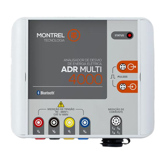
- Page 12 4000 ADR MULTI 4-mm safety terminals Terminal Function Phase A voltage input Black Phase B voltage input Yellow Phase C voltage input Blue Neutral reference input Figure 8-9 Voltage input terminals. Table 8-5 Voltage input terminals. 8.1 - OPERATION OPTIONS According to the need and application, it is possible to choose some options that fa- cilitate and further enhance device performance.
- Page 13 Meter pulses can be captured in three optional manners: in the first option, we have the MSM 4000 sensors for automatic pulse capturing for electromechanical or electronic meters, in which the sensor is fixed to the front part of the meter through suction cups, and can detect the disk mark or the LED pulse;...
-
Page 14: Connection System
9 - CONNECTION SYSTEM ADR Multi 4000 is simply a meter of multiple electric quantities, for use in electric power distribution systems. As a basic operation principle, we have the collection of information on electric quantities by metering the voltage and electric current in... - Page 15 A - Single-phase connection – 1 Phase + Neutral + 1 CT. Figure 9-1 Single-phase connection system. B - Two-phase connection – 2 Phases + Neutral + 2 CTs or 1 Phase 3 Wires. Figure 9-2 Two-phase connection.
- Page 16 4000 ADR MULTI C - Balanced three-phase connection – 1 Phase + Neutral + 1 CT. Figure 9-3 Balanced three-phase connection. D - Three-phase connection without neutral – 3 Phases + 2 CTs Figure 9-4 Three-phase connection without neutral with 2 CTs.
- Page 17 E - Three-phase connection without neutral – 3 Phases + 3 CTs. Figure 9-5 Three-phase connection without neutral with 3 CTs. F - Three-phase connection – 3 Phases + Neutral + 3 CTs. Figure 9-6 Three phase connection.
- Page 18 4000 ADR MULTI G - Indirect three phase connection – 3 Phases + Neutral + 3 CTs. Figure 9-7 Indirect three phase connection. H - Indirect three phase connection - 3 Phases + 2CTs. Figure 9-8 Indirect three phase connection 2 elements.
-
Page 19: Features
To start using it, the application must be opened by clicking the ADR Multi 4000 icon in your An- droid® device. A login screen is presented,and then, the fields user and password are request- ed. - Page 20 “Start” icon on the upper left corner.Using the side menu, it is possible to browse through the ADR Multi 4000 func- tionalities, such as Parameters and Modules, among others. Figure 10-3 shows the screen containing the side menu.
- Page 21 To implement the meter analysis, ADR Multi 4000 simultaneously conducts its own metering of the energy consumed and the reading of the consumption recorded by the meter, in the same period, and calculates the error in the form of percentage deviation.
- Page 22 4000 ADR MULTI This data can be visible or hidden according to the previously established settings and parameters. A full list of fields is shown in table 10-1. Field Description Service Order No. of the inspection Service Order Client Code Code of the client being inspected Consuming Unit No.
- Page 23 After properly configuring the parameters, if the connection with ADR Multi 4000 is active, click on “next” to start the test. If all mandatory fields are completed and the minimum time for testing is above the pre-configured limit, then the application will...
- Page 24 4000 ADR MULTI Figure 10-5 illustrates the tab indicating the averages and totals measured quanti- ties. Figure 10-5 Tab screen of Averages and Totals. Figure 10-6 shows the tab screen of instant measures by phase. Figure 10-6 Tab screen of instant measures by phase.
- Page 25 Figure 10-7 shows the instant visualization screen in the form of linear charts. Figure 10-7 Linear chart screen. Finally, figure 10-8 illustrates the phasor diagram tab. Figure 10-8 Phasor diagram screen.
- Page 26 ADR Multi 4000 must start measuring consumption. Sim- ilarly, a pulse is given to mark the end of counting. In this way, ADR Multi 4000 interprets that, during the measuring period between the start and end pulses, the...
- Page 27 Supplementarily, when moving the screen to the left, it shows the data and parame- ters used in this test, as seen in figure 10- To save the test data in the form of a struc- tured report, click on the “Save”, so that the report can be accessed from the “Reports”...
- Page 28 4000 ADR MULTI The report screen lists all reports saved on the device. It is possible to narrow the list of reports using filtering criteria, such as ap- proval, date, consuming unit No., among oth- ers. To filter the report list, it is necessary to use the “Search”...
- Page 29 10.5 - HELP This function opens up the operation manual available in the application. Visual- ization is obtained using a PDF reader. Should it be impossible to view the file, it is necessary to check compatibility of the Android® versions. For more information please contact the Montrel team.
- Page 30 4000 ADR MULTI • Keep logged in after closing the application If enabled, once you have logged in to the application, it will not be necessary to log- in again next time you access the application, which will remain as is until the “exit” option on the application is enabled.
- Page 31 • Minimum estimated time This parameter defines the minimum estimated time that each test must meet. This prevent very quick tests from being conducted and ensures that the minimum time is met. The recommended initial factory parameter is 60 seconds, which can be changed when convenient.
- Page 32 4000 ADR MULTI 10.6.3 - MODULES On the modules screen, the user defines which information on the meter inspection must be displayed in the test configuration, in the result of the tests, and in the inspec- tion report. Figures 10-16, 10-17, and 10- 18 show an example of the three configu- rable modules.
- Page 33 Figure 10-18 Test report module. Table 10-3 provides the description of each parameter subject to configuration by the user.
- Page 34 4000 ADR MULTI Table 10-3 Configuration parameters.cc Service Enables inclusion of the service order ID Order during test performance. Client Enables inclusion of the client code ID Code during test performance. Consuming Enables inclusion of the consuming unit No. Unit No. ID during test performance.
- Page 35 Enables display of the ID of the type of Single-phase 1Ph+N+1CT Type of connection connection utilized, on the test result Two-phase 2Ph+N+2CT page. 1Ph+N+1CT Balanced three-phase Three-phase w/o neutral 3Ph+2CT Three-phase w/o neutral 3Ph+2CT Three-phase 3Ph+N+3CT Type of Enables display of the ID of the type of Direct Metering utilized metering, on the test result page.
- Page 36 Enables display of the value of the energy Recorded registered in the metering period, on the test result page. Serial No. Enables display of the ADR Multi 4000 serial No. on the test result page. Calibration Enables display of the meter report No.
- Page 37 Logo Enables display of logo on the body of the report. Report No. Enables display of the inspection report No. on the body of the report. Date and Time Enables display of the name of the person in the person in charge of the inspection, on the body of the report.
- Page 38 4000 ADR MULTI Type of Metering Enables display of the identification of the Direct type of metering performed, on the body Indirect of the report PT Ratio Enables display of the considered potential transformation ratio, on the body of the report CT Ratio Enables display of the current considered transformation ratio,...
- Page 39 Active power [kW] Enables display of the measured active power by phase, on the body of the report. Reactive power Enables display of the measured reactive [kvar] power, by phase, on the body of the report. Apparent power Enables display of the measured apparent [kVA] power, by phase, on the body of the report.
- Page 40 In this tab, the user selects the ADR which the application should commu- nicate with to perform the tests. All ADR Multi 4000 within reach will be listed always keeping the standard: “AM4-XXXX” (XXXX is equivalent to the ADR serial No.). Those devices that have already been previously paired, even if out of reach, are also listed and classified as “Paired”.
- Page 41 It is possible to remove the pairing of these devices by simply clicking on the “trash bin” icon and confirming the removal of pairing. Devices within reach, though not yet paired are listed and classified as “Unpaired”. To pair a device that has not yet been paired, simply click on the Bluetooth icon and pro- vide the individual pairing PIN, supplied with the device.
- Page 42 10.6.6 - USER This tab gathers information on each in- dividual (or group of individuals) that will operate ADR Multi 4000. The user is identi- fied with a registration name and number. This is an optional number to identify the operator, who has a password to access the application.
- Page 43 needed. To remove a user, select the “Re- move” option and confirm user removal. This screen is shown in figure 10-22. Each user must be linked to a profile, which defines the operation functionalities to which the user will have access. To create a new user, click on the “New”...
- Page 44 4000 ADR MULTI 11 - ACCESSORIES Included • Set of three 200A articulated-core CTs clamps; • Sensor for capturing infrared (optical port) MSP 4000; • Manual external trigger for counting disk rotations and • pulses of LED model MDE 4000; •...
- Page 45 The content of the ADR Multi 4000 operation manual is subject to change without prior notice. Serial Number:...
- Page 46 4000 ADR MULTI NOTES...
- Page 47 NOTES...
- Page 48 45 Maria Caporali St Mogi Guacu | SP Brazil Zip Code 13845-021 +55 19 3861 3070 "Innovation, that is montrel@montrel.com.br our differential" www.montrel.com.br...
Need help?
Do you have a question about the ADR Multi 4000 and is the answer not in the manual?
Questions and answers