Table of Contents
Advertisement
RangeFinder
User manual
Project/Product
SM-140 - RangeFinder
Classification
Open
Summary:
The SM-140/02 RangeFinder is a unique high-performance remote sensor for measurement of air
gap, water level, draught and non-directional wave parameters. It utilizes a microwave radar-based
FMCW (Frequency Modulated Continuous Wave) sweep method for measuring air gap. When
delivered with the optional embedded MRU (Motion Reference Unit) to compensate for vessel
heave, the sensor is named SM-140 WaveFinder. For simplicity the name RangeFinder is used
throughout this document.
The sensor enables data to be easily accessible both locally and remotely using modern IoT
technologies.
The sensor is essential for several types of operations and can be integrated both with local and
remote systems. It can also be complimented with various value adding cloud services from Miros.
This manual provides information for installation, operation and user maintenance.
Revision No.
2
Date
2018-12-19
Prepared by
Torbjørn Eide
Checked by
Gunnar Prytz
Approved by
Torbjørn Eide
50 pages
Description:
Issued for information
Advertisement
Table of Contents

Summary of Contents for Miros SM-140 Series
- Page 1 The sensor is essential for several types of operations and can be integrated both with local and remote systems. It can also be complimented with various value adding cloud services from Miros. This manual provides information for installation, operation and user maintenance.
- Page 2 Blank page.
-
Page 3: Table Of Contents
Warnings ..........................6 Abbreviations and definitions ....................6 Reference documentation ....................7 How to contact Miros AS ..................... 7 Quick start guides for advanced users How to log on ........................8 How to get data (NMEA and/or SER formats) ..............8 How to configure using the Web GUI .................. - Page 4 PMIRW – RangeFinder water level and wave parameters ..........46 PMIRS – RangeFinder wave spectrum, water level and wave parameters ..... 47 PMIRWD – RangeFinder water level, wave and draught parameters ......48 PMIRM – RangeFinder motion..................50 Miros AS Page 4 of 50 Revision 2...
-
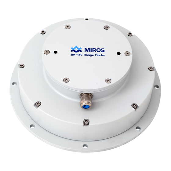
Page 5: Introduction
It can also be complimented with various value adding cloud services from Miros. This manual provides information for installation, operation and user maintenance. Wide beam model SM-140/W/02 Narrow beam model SM-140/N/02 Figure 1.1 SM-140 RangeFinder Miros AS Page 5 of 50 Revision 2... -
Page 6: Warnings
Do not attempt to dismantle the unit. The sensor is a precision instrument and shall not be subject to field service by operator's personnel unless pre-approved by Miros. Do not modify or substitute parts in the instrument. Contact Miros Support or Miros’ representative for repairs. -
Page 7: Reference Documentation
SM-140/009/DR SM-140/N/01 RangeFinder - General arrangement SM-140/02 RangeFinder - Data sheet SM-140/02 WaveFinder - Data sheet SM-140/006/DD SM-140 - EC Declaration of Conformity (CE Marking) How to contact Miros AS Norway Corporate headquarters Miros AS Miros Scotland Ltd. Solbråveien 20 Aberlan House. -
Page 8: Quick Start Guides For Advanced Users
Type help to list commands/command groups. Type command group to list sub-commands etc., e.g. config or config site. To change a parameter, add a value to the command/sub-command, e.g. config site height 30 to set sensor mounting height to 30 m. Miros AS Page 8 of 50 Revision 2... -
Page 9: Product Overview
SM-140 - RangeFinder (User manual) Product overview General description The Miros SM-140 RangeFinder is a microwave radar-based sensor operating at 9.6 GHz centre frequency. It uses the FMCW principle to measure the vertical distance from the sensor antenna to the water surface. - Page 10 The digital signal output may either be continuous at a user selectable rate, or single measurements in response to user request. The sensor transmits Miros proprietary NMEA formats over TCP/IP port 4001. The old SER formats may also be selected by the user for compatibility with previous models of the Miros SM-140 RangeFinder.
- Page 11 (DDS). A DDS has many advantages over its analogue counterpart, the PLL; much better frequency agility, improved phase noise, and precise control of the output phase across frequency switching transitions. Figure 3.4 SM-140 RangeFinder functional block diagram Miros AS Page 11 of 50 Revision 2...
-
Page 12: Principles Of Operation
The sensor unambiguous range is the theoretical maximum range for a given FMCW waveform. The sensor range must for practical reasons be slightly less than the unambiguous range. The number of range cells required to cover the sensor range is automatically calculated. Miros AS Page 12 of 50 Revision 2... - Page 13 (e.g. if only a certain signal level shall be processed). Range cells outside a predetermined range can be neglected for applications that shall work within a restricted range. Figure 3.7 Range tracking window Miros AS Page 13 of 50 Revision 2...
- Page 14 Each wave bin represents a wave period, e.g. for frequency bin no. 4 and 0.0078 Hz resolution: Wave period = = 32 s Freq bin x resolution 4 x 0.0078 Hz Similarly, wave bin 26 represents the mean wave period of 5 s. Miros AS Page 14 of 50 Revision 2...
- Page 15 (after detrending and interpolation). Before calculating the individual wave periods (1/cycle), heights, crests and troughs, wavelets (small capillary waves) are ignored. Figure 3.10 Wave profile For wave parameters calculated directly from the wave time series, refer to Appendix A2. Miros AS Page 15 of 50 Revision 2...
-
Page 16: Sensor Location And Orientation
Miros recommends use of the MP-404 Bolting Kit for proper installation. The bolting kit includes necessary bolts, insulation washers and sleeves for a four-hole fixation. Miros MP-327 Mounting Bracket is available as option for easy installation to a handrail or similar. Miros AS... - Page 17 Cable entry is via a M20 cable gland from the side. Cable OD 5 - 14 mm (9 - 14 mm without inlet insert). Figure 3.12 Mechanical installation - SM-140 wide beam RangeFinder Miros AS Page 17 of 50 Revision 2...
- Page 18 Cable entry is via a M20 cable gland from the side. Cable OD 5 - 14 mm (9 - 14 mm without inlet insert). Figure 3.13 Mechanical installation - SM-140 narrow beam RangeFinder Miros AS Page 18 of 50 Revision 2...
-
Page 19: Electrical Installation
An external T2A overcurrent protector is mandatory for installations in compliance with the CE marking requirements. The SM-140 RangeFinder is normally installed with a short cable to a local junction box. Miros recommends that an external T2A overcurrent protector (fuse) is mounted in the local junction box. - Page 20 Optionally a four pair BFOU cable can be used for serial communication. Open top lid for access to terminals. The terminals are part of the EU-051 Connector Unit, with signal description as shown on the next page. Miros AS Page 20 of 50 Revision 2...
- Page 21 It is thus important to connect a bonding wire from the RangeFinder either directly to the platform or plant metal structure or via suitable bonding point. Miros recommends a 16 mm2 YE/GN bonding cable for this purpose. Miros AS...
- Page 22 RS-422 RxA (Rx-) Pair 1a (WH) +24 V power supply Pair 1b (BN) 0 V (GND) power supply Screen Screen Insulated Pair 4b (RD) Not used Table 4: External connection – RS422 Miros AS Page 22 of 50 Revision 2...
- Page 23 Pair 3a (GY) Not used Insulated Pair 3b (PK) Not used Insulated Pair 4b (RD) Not used Table 5: External connection – RS232 Note! Maximum cable length for RS232 is 25 m. Miros AS Page 23 of 50 Revision 2...
-
Page 24: Operation And Configuration Using Local Gui
Turn on/off visual alerts (if enabled in Config->Display) Theme (night/dark and day/light) can be changed by toggling the theme icon (upper right corner). The two themes are shown below. Figure 4.1 Theme example – day (left) and night (right) Miros AS Page 24 of 50 Revision 2... -
Page 25: Start-Up Check
(for the last 60 seconds). The range spectrum quality (peak divided by background) is shown in the Quality Factor chart (for information only, use with care – the value is very dependent on the site/configuration). Miros AS Page 25 of 50 Revision 2... -
Page 26: Wave Tab
Wave parameters calculated from the wave spectrum may or may not be equal to the equivalent parameter calculated directly from the time series. Both the method and the algorithms are different and the difference between the parameters will change with the sea state. Miros AS Page 26 of 50 Revision 2... -
Page 27: Wl + Draught Tab
History window, Wave Profile, Water Level and Draught charts show the data. The Status window shows the internal temperature and humidity. Figure 4.4 WL + Draught tab example Miros AS Page 27 of 50 Revision 2... -
Page 28: Motion Tab
Wave Profile (chart) • Roll and Pitch (chart) The motion parameters are for information only. Only heave (displacement) is used for motion compensation on vessels and floating platforms. Figure 4.5 Motion tab example Miros AS Page 28 of 50 Revision 2... -
Page 29: Site Configuration Tab
WaveFinder – Platform (for wave measurements on large vessels/platforms) For convenience, the figure to the right shows the results of the configuration (including calculated footprint diameters for the specific setup). Figure 4.6 Config -> Site tab example Miros AS Page 29 of 50 Revision 2... -
Page 30: Network Configuration Tab
Config -> Network tab shown in figure below. DHCP can be enabled to allow dynamic IP address allocation. The Cloud enabled selector and the Cloud connection string can only be used by Miros personnel. Figure 4.7 Config -> Network tab example... -
Page 31: Output Configuration Tab
Data is available both over TCP/IP port 4001 on the Ethernet interface and RS232/RS422 simultaneously. Figure 4.8 Config -> Output tab example Tick off one or more of the Miros proprietary NMEA sentences. For description of the NMEA output formats, refer to Appendix A for details. •... -
Page 32: Time Configuration Tab
4.10 Wave configuration tab Do not alter these settings unless you are a skilled user. Wrong settings can cause the algorithms to fail, hence unreliable or no data will be the result. Miros AS Page 32 of 50 Revision 2... -
Page 33: 4.11 Wl + Draught Configuration Tab
This menu is used to set the water level and draught Reference levels and Time constants. For convenience, the figure to the right shows the results of the configuration. Figure 4.10 Config -> WL + Draught tab example Miros AS Page 33 of 50 Revision 2... -
Page 34: 4.12 Advanced Configuration Tab
Overview tab) Tracking should be turned off for wave measurements (may introduce low frequency noise in the wave spectrum if signal is lost) Figure 4.11 Config -> Advanced tab example Miros AS Page 34 of 50 Revision 2... -
Page 35: 4.13 Display Tab
Note that it is likely that you must refresh the web browser for the changes to take effect on the GUI. Figure 4.13 Config -> Firmware upgrade tab example Miros AS Page 35 of 50 Revision 2... -
Page 36: Maintenance
Troubleshooting and repair In case irregularities are detected from day-to-day use or as part of the periodic inspection, please contact Miros Support. It is recommended to send the complete unit to Miros for repair in case a malfunction is detected. -
Page 37: Technical Data
Update interval: 10 s. Observation time (averaging time): 20 min default Note 3: Depending on length of periodogram (ref. Config -> Wave) Note 4: With optional MRU the frequency range is 0,03 – 0.5 Hz Note 5: Depending on mounting height Miros AS Page 37 of 50 Revision 2... -
Page 38: Electrical Data
Up to 50 Hz over TCP/IP or serial Versions Range 3 – 95 m, narrow beam (5 deg) SM-140/N/02/90 SM-140/W/02/20 Range 1 - 23 m, wide beam (10 deg) SM-140/xx/02/xx/RSxxx RS-232 and RS-422 Miros AS Page 38 of 50 Revision 2... -
Page 39: Accessories And Options
SM-140 - RangeFinder (User manual) Accessories and options MP-327 Mounting Bracket EA-116/xx Junction Box Cloud services Miros AS Page 39 of 50 Revision 2... -
Page 40: Appendix A Proprietary Nmea Formats
Mean zero up-crossing period (T ) (s) x.x,x.x 29-30 Mean period (T ) (s) x.x,x.x 31-32 Maximum wave period (T ) (s) x.x,x.x 33-34 Wave period of maximum wave height (T ) (s) x.x,x.x Hmax Miros AS Page 40 of 50 Revision 2... -
Page 41: Pmirwp - Wave Parameters From Time Series
Day, 01 to 31 Month, 01 to 12 Year yyyy Sequence number (1) 07-08 Total numbers of samples in analysis (N x,x.x (see note 1) 09-10 Filter method used before analysis (F x,x.x Miros AS Page 41 of 50 Revision 2... - Page 42 57-58 Observation period (O ) (minutes) x.x,x.x <CR><LF> Table 7: PMIRWM sentence NOTE 1 Each parameter is followed by a status code (value between 0.0 and 1.0). The higher value the better. Miros AS Page 42 of 50 Revision 2...
-
Page 43: Pmirld - Wave Spectrum
The number of data fields, N is given by the number of frequencies and number of directions: N = Number of frequencies * (1 + Number of directions) Status code, heading and position data may be omitted. Miros AS Page 43 of 50 Revision 2... -
Page 44: Pmirr - Rangefinder Data
MRU status code (optional) A (see note 3) Checksum delimiter and checksum value <CR><LF> Table 9: PMIRR sentence Fields 08-14 can be excluded in the sentence if MRU data are not transmitted. Miros AS Page 44 of 50 Revision 2... - Page 45 Range quality indicator (no of valid samples divided by total no of samples since last output), [0.00 ...1.00] NOTE 3 MRU status codes. Code Description Data valid Data valid, but unstable No data (no values are transmitted) Table 11: MRU status codes Example: $PMIRR,20100916,113442.751,21.990,20.995,A,0.88,0.1,0.2,0.3,0.4,0.5,1.507,A*71<CR><LF> Miros AS Page 45 of 50 Revision 2...
-
Page 46: Pmirf - Rangefinder Spectrum
Time stamp (hours, minutes, seconds and milliseconds) hhmmss.sss Water level reference (Hslu0). Set by user. Water level (Hslu1) Significant wave height (Hm0) Maximum wave height (Hmax) Mean zero up-crossing period (Tm02) Miros AS Page 46 of 50 Revision 2... -
Page 47: Pmirs - Rangefinder Wave Spectrum, Water Level And Wave Parameters
06-N+6 Wave spectrum (N values) N+07 Water level reference (Hslu0). Set by user. Water level (Hslu1) Significant wave height (Hm0) N+10 Maximum wave height (Hmax) N+11 Mean zero up-crossing period (Tm02) Miros AS Page 47 of 50 Revision 2... -
Page 48: Pmirwd - Rangefinder Water Level, Wave And Draught Parameters
Mean zero up-crossing period (Tm02) Peak period (Tp) Spectrum status code A (see note 3) Spectrum quality indicator x.x (see note 4) Checksum delimiter and checksum value <CR><LF> Table 16: PMIRW sentence Miros AS Page 48 of 50 Revision 2... - Page 49 Description Data valid Low quality data Table 18: Range spectrum status codes NOTE 4 Range quality indicator (no of valid samples divided by total no of samples since last output), [0.00 ...1.00] Miros AS Page 49 of 50 Revision 2...
-
Page 50: Pmirm - Rangefinder Motion
NOTE 1 If external MRU (Seatex MRU 5/H is used), roll and pitch angles are in radians. NOTE 2 MRU status codes. Code Description Data valid Data valid, but unstable Table 20: MRU status codes Miros AS Page 50 of 50 Revision 2...
Need help?
Do you have a question about the SM-140 Series and is the answer not in the manual?
Questions and answers