
Summary of Contents for Oceanic Systems NMEA2000 5971
- Page 1 NMEA2000® NAVIGATION LIGHT CONTROLLER Part Numbers: 5971 NAV LIGHT CONTROLLER EXPANSION UNIT Part Numbers: 5972 Installation and Operation Manual 5971 5972 Document revision 1...
-
Page 2: Table Of Contents
Introduction............Product Features..........Installation............Unpacking The Box..........Mounting the unit..........Connecting the NMEA2000® Cable....... Connecting the LED Power Input Cables to the unit Connecting the LED Navigation Lamps to the unit.. Panel Controls and Indicators......Calibration............LED Power on Hours........... Maintenance............. -
Page 3: Introduction
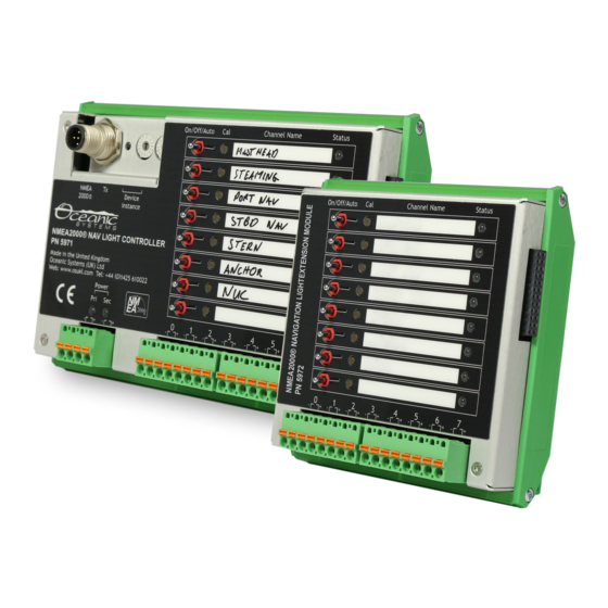
INTRODUCTION The Oceanic Systems NMEA2000® Navigation Light Controller Part No. 5971 and Nav Light Controller Expansion Units Part No. 5972 are designed to control up to 24 Navigation Light LED Channels on a NMEA2000® network. The 5971 is powered from the NMEA2000® network and has a primary and a secondary 12 or 24 Volt DC power connection for the navigation LEDS. -
Page 4: Installation
INSTALLATION 2.1 UNPACKING THE BOX You will find the following items in the 5971 shipping box: 1 x 5971 NMEA2000® Navigation Light Controller 1 x 5971/5972 Installation and Operation Manual (This document) You will find the following items in the 5972 shipping box: 1 x 5972 Nav Light Expansion Unit 1 x 5971/5972 Installation and Operation Manual (This document) 2.2 MOUNTING THE UNIT... -
Page 5: Connecting The Nmea2000® Cable
33 mm 24.5 mm 57 mm Dimension 115 mm diagram of 5972 2.3 CONNECTING THE NMEA2000® CABLE The unit is connected to the NMEA2000® network by the 5 way micro C socket on the front. Carefully attach the network drop cable to this plug and hand tighten until it is fully seated. Take care to match the orientation of the pip inside the socket to the recess inside the drop cable plug. -
Page 6: Connecting The Led Power Input Cables To The Unit
2.4 CONNECTING THE LED POWER INPUT CABLES TO THE UNIT The unit has both a primary navigation lamp power connection and a secondary power connection with automatic fall back if the primary power fails. Each power source has a local green LED indicating power good from that source. -
Page 7: Panel Controls And Indicators
Note that LED connections are polarity sensitive and must be correctly wired to work. Each connection can supply 750mA with a maximum total current from each unit of 2.5 Amps. After connecting the LEDs the unit should be calibrated for each channel which allows the unit to learn the current draw of each channel and warn if the LED has a partial failure or the connection is broken or corroded. -
Page 8: Calibration
Each channel also has an channel status indicator LED that shows the following characteristics: LED Characteristics Meaning No LED illuminated Channel switched OFF Green LED Flashing Channel switched ON but NOT calibrated Solid Green LED Channel calibrated and switched ON Red LED flashing Channel switched ON but over hours Solid Red LED... -
Page 9: Operation
OPERATION Ensure that the NMEA2000® network cable is securely attached and that the Device Instance rotary switches have been set to a valid and unique Device Instance on the network. The switches are marked with a Hexadecimal notation, so each switch has 16 possible positions. The combination of the two switches can be set from “00”... -
Page 10: Technical Specification
TECHNICAL SPECIFICATION Design Standards Parameter Comment NMEA2000® Certified Maritime Nav and RadioComm Equipment Designed to IEC61162-3 Maritime Nav and RadioComm Equipment Designed to IEC60945 CE and FCC Electromagnetic Compatibility Class Approval Designed to DNV Navigation Light Controller NMEA2000® Parameter Group Numbers (Pgns) Description PGN # PGN Name... - Page 11 Mechanical Parameter Value Comment 5971 Weight 395g DIN Rail Mount 5971 Size 177mm x 118mm 5972 Weight DIN Rail Mount 5972 Size 115mm x 118mm Environmental Parameter Value IEC 60945 Classification Protected Degree of Protection IP40 Operating Temperature -25°C to 55°C Storage Temperature -40°C to 70°C Relative Humidity...
-
Page 12: Warranty
Systems sole obligation hereunder, provided product is returned pursuant to the return requirements below, shall be limited to the repair or replacement, at Oceanic Systems option, of any product not meeting the above limited warranty and which is returned to Oceanic Systems; or if Oceanic Systems is unable to deliver a replacement that is free from defects in materials or workmanship, Purchaser’s... -
Page 13: Technical Support
Email: sales@osukl.com Web: www.osukl.com Copyright © 2020 Oceanic Systems (UK) Ltd. All rights reserved. Our policy is one of continuous product improvement so product specifications are subject to change without notice. Oceanic Systems products are designed to be accurate and reliable.
Need help?
Do you have a question about the NMEA2000 5971 and is the answer not in the manual?
Questions and answers