Advertisement
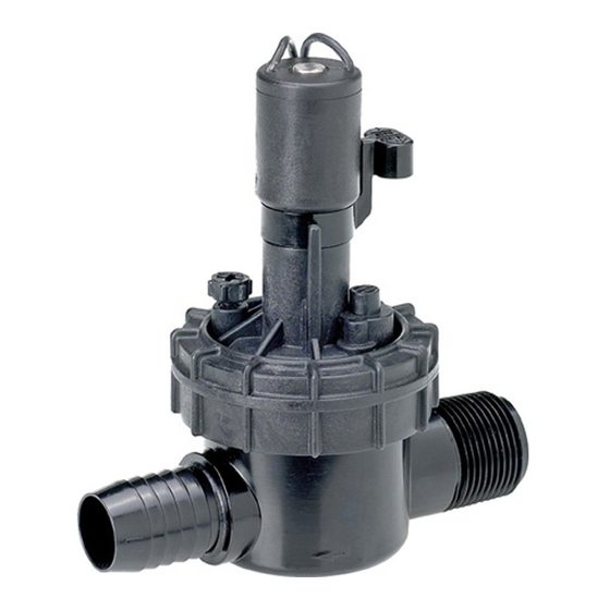
Manual Operation (Figure 4)
• Bleed Screw (external bleed): To open the valve, turn
the Bleed Screw counterclockwise one full turn or
until water begins discharging from the port.
Note: Removing the bleed screw is not required but
can be removed to help flush debris from the upper
diaphragm area.
To close the valve, turn the bleed screw clockwise
until it stops. Do not over-tighten!
• Bleed Handle (internal bleed): To open the valve, move the Bleed Handle counterclockwise to the
stop. To close the valve, move the handle clockwise until resistance is felt. Do not over-tighten!
• Flow Control Adjustment: With the valve operating, use a small screwdriver to turn the flow
control screw clockwise to decrease flow or counterclockwise to increase flow.
Note: The flow control screw requires approximately seven turns to adjust from maximum to
minimum flow.
Caution: Do not use the flow control to shut off the valve. Do not force the flow control
screw past the end of normal adjustment travel. Damage can occur.
The Toro Promise — Limited One-Year Warranty
The Toro Company and its affiliate, Toro Warranty Company, pursuant to an agreement between
them, jointly warrants, to the owner, each new piece of equipment against defects in material and
workmanship for the period of one year from the date of purchase.
Neither Toro nor Toro Warranty Company is liable for failure of products not manufactured by
them even though such products may be sold or used in conjunction with Toro products.
During such warranty period, we will repair or replace, at our option, any part found to be
defective.
Return the defective part to the place of purchase.
Our liability is limited solely to the replacement or repair of defective parts. There are no other
express warranties.
This warranty does not apply where equipment is used, or installation is performed, in any manner
contrary to Toro's specifications and instructions, nor where equipment is altered or modified.
Neither Toro nor Toro Warranty Company is liable for indirect, incidental or consequential
damages in connection with the use of equipment, including but not limited to: vegetation loss,
the cost of substitute equipment or services required during periods of malfunction or resulting
non-use, property damage or personal injury resulting from installer's negligence.
Some states do not allow the exclusion or limitation of incidental or consequential damages, so the
above limitation or exclusion may not apply to you.
All implied warranties, including those of merchantability and fitness for use, are limited to
the duration of this express warranty.
Some states do not allow limitations of how long an implied warranty lasts, so the above limitation
may not apply to you.
This warranty gives you specific legal rights and you may have other rights
which vary from state to state.
© 2008 The Toro Company • Irrigation Division • Assembled in Mexico
Figure 4
Flow Control
Screw
Bleed
Bleed
Screw
Handle
Form No. 373-0377 Rev. C
1" In-line Valve Model 53799
Installation Guide
-
The Toro 1" in-line electric valve is designed for use in an automatic
sprinkler system controlled by a 24 V a.c. sprinkler system timer.
The valve features manual flow control adjustable down to zero flow
and manual bleed control which enables the valve to be operated
without the use of the timer. The 53799 valve is designed for
poly pipe connections. This valve is generally installed below
grade, grouped with other valves in a manifold arrangement and
housed in a protective
valve box.
Important: This valve does not provide backflow
protection. A backflow prevention device installed
between the 1" in-line valve(s) and the water source point
of connection is required in most areas to prevent back-siphoning of contaminants through the
sprinkler system into the potable water supply. The Toro 1" Pressure Vacuum Breaker (PVB), model
number 53300, is specifically designed for this purpose. Before connecting your irrigation system to
the potable water supply, consult with your local water utility department for information regarding
backflow prevention requirements. Where local water pressure exceeds 70 psi, a pressure regulator
should be used. (See Uniform Plumbing Code, Sec. 1007 [b].) It is advisable to use a regulator with
any automatic valve to assure long life as well as uniform and controllable operation.
Valve Specifications:
Operating Pressure: 20–150 PSI (70 PSI maximum recommended)
Flow Range: 0.25–30 GPM
Solenoid:
24 V a.c., 60 Hz (nominal)
19 V a.c., 60 Hz (minimum)
Inrush: 0.40 amps, 9.6 VA @ 24 V a.c., 60 Hz
Holding: 0.20 amps, 4.8 VA @ 24 V a.c., 60 Hz
Friction Loss:
GPM Flow
0.25
5
10
15
PSI Loss
2.0
3.5
4.0
3.0
Installation Procedure
Note: To ensure ease of installation and optimum valve performance, please read through the
following instructions completely before starting the installation procedure.
Step 1-Route 1" schedule 40 PVC pipe from the backflow preventer or system
shut-off device to the valve location. Flush the supply line thoroughly!
Caution: Dirt, rocks and debris entering the valve can damage the valve and/or cause the
valve to malfunction.
Step 2-The instructions and illustrations on the next page provide the most commonly recommended
methods of installing in-line valves in a manifold arrangement.
RELEASED Version
-
53799
20
30
3.3
6.2
©Toro 2008-2008
Advertisement
Table of Contents

Related Manuals for Toro 53799


Summary of Contents for Toro 53799
- Page 1 The Toro 1" Pressure Vacuum Breaker (PVB), model Caution: Do not use the flow control to shut off the valve. Do not force the flow control number 53300, is specifically designed for this purpose.
- Page 2 • Model 53799 Installation (Figure 1 & 2) Figure 1 1 1/4" Polyethylene Pipe Step 1-Apply three complete wraps of PTFE tape to the threaded male ends of the valves. (Poly Pipe) Caution: Use only PTFE tape on threaded connections. Pipe dope and other types of pipe thread sealants can damage plastic threads.
Need help?
Do you have a question about the 53799 and is the answer not in the manual?
Questions and answers