Table of Contents
Advertisement
Advertisement
Table of Contents

Related Manuals for SST 5136-PFB-VME

Summary of Contents for SST 5136-PFB-VME
- Page 1 (217) 352-9330 | Click HERE Find the Molex / Woodhead / SST 5136-PFB-VME at our website:...
- Page 2 5136-PFB-VME Hardware Guide Version 2.02 50 Northland Road Waterloo, Ontario, CANADA N2V 1N3 Tel: (519) 725-5136 Fax: (519) 725-1515 www.mySST.com...
- Page 3 All rights reserved. No portion of this document may be reproduced in any form without the prior written permission of Woodhead Canada Limited. SST is a trademark of Woodhead Industries, Inc. All other trade names are trademarks or registered trademarks of their respective companies.
-
Page 4: Table Of Contents
Contents Introduction ..............1 Purpose ............2 Conventions........... 2 1.2.1 Style ............2 1.2.2 Special Notation ........2 Card Overview ..........3 Reference Documents ........4 Warranty ............5 Technical Support ......... 6 1.6.1 Before you call for help......6 1.6.2 Getting Help .......... - Page 5 2.6.2 Loading the VMEPROFI Module into Flash Memory from the Serial Port ........19 2.6.3 Running the VMEPROFI module ..20 2.6.4 Installing the Files for the SST ProfiBus Configuration Tool ....22 2.6.5 Installing the Files for COM PROFIBUS ........22 Configuring the VMEPROFI Module ...
- Page 6 Contents Card Registers ............. 33 Short I/O Registers ........34 3.1.1 Board Control register at BASE+1 36 3.1.2 Memory Control register at BASE + 3 ..........35 3.1.3 Memory Page register at BASE + 5 ..........36 3.1.4 Interrupt Control register at BASE + 7 ..........
- Page 7 5136-PFB-VME Hardware Manual...
-
Page 8: Introduction
Introduction This chapter describes the following: • the purpose of the manual • the style conventions used in the manual • an overview of the card • reference material • warranty and technical support information... -
Page 9: Purpose
5136-PFB-VME Hardware Manual Purpose This document is a hardware user’s guide for the SST 5136-PFB-VME interface card. This card allows an application running on a VMEbus host computer to communicate with ProfiBus Networks using Profibus DP and FDL. Conventions 1.2.1 Style The following conventions are used throughout the manual: •... -
Page 10: Card Overview
Introduction Card Overview The 5136-PFB-VME card can: • act as a DP slave • act as a DP master • send and receive FDL (layer 2) messages The card supports simultaneous operation in all these modes. The card supports the standard ProfiBus baud rates of 9.6K, 19.2K, 93.75K, 187.5K, 500K, 750K, 1.5M, 3M, 6M and 12M baud. -
Page 11: Reference Documents
5136-PFB-VME Hardware Manual Reference Documents For information on ProfiBus, refer to one of the following: • ProfiBus standard DIN 19 245 parts 1, 2 and 3. Part 1 describes the low level protocol and electrical characteristics, part 2 describes FMS, part 3 describes DP •... -
Page 12: Warranty
Maximum liability of SST is the cost of the product(s). Product Returns If it should be necessary to return or exchange items, please contact SST for a Return Authorization number. SST, a division of Woodhead Canada Ltd. -
Page 13: Technical Support
1.6.2 Getting Help Technical support is available during regular business hours by telephone, fax or email from any SST office, or from the company Web site at www.mySST.com. Documentation and software updates are available on our Web site. -
Page 14: Installation
Installation This chapter describes the following: • application design considerations • installation • setting the switches and jumpers on the card • installing the card software • connecting the card to a ProfiBus network • downloading software modules to shared memory or flash memory on the card... -
Page 15: Handling Precautions
Application Design Considerations 2.2.1 Running from Flash or RAM? When designing an application for the 5136-PFB-VME, the first decision you have to make is whether you want to load and run the card software from flash memory or by downloading it from the host computer. -
Page 16: Which Addressing Mode
Installation In general, if you have access to a file system, you should load and configure the card from the host. Running from flash is preferred in embedded environments or whenever it is difficult to send files to the card, such as a VME based PLC. -
Page 17: Board Layout
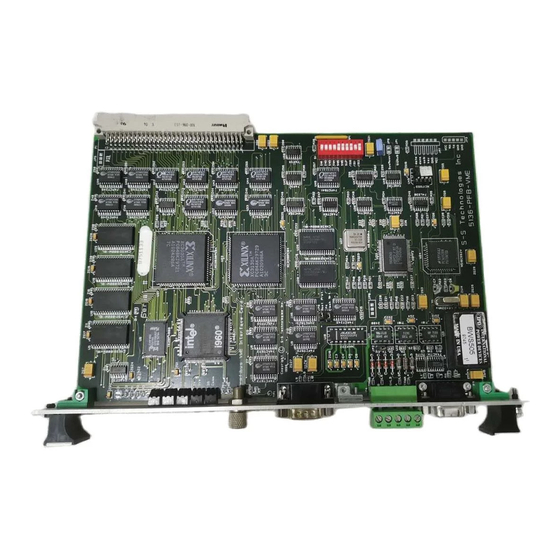
5136-PFB-VME Hardware Manual 2.3.1 Board Layout... -
Page 18: Setting The Switches
Installation Setting the Switches The card has a 10-position DIP switch that must be set before installing the card. Position Purpose Refer to Section short I/O address 2.4.1 access privilege 2.4.2 8-10 interrupt 2.4.3 2.4.1 Setting the Short I/O Base Address The 1 Kbyte block of short address space occupied by the card is located on a 1 Kbyte boundary at an address selected by positions 1 through 6 of the switch. - Page 19 5136-PFB-VME Hardware Manual The following table shows the possible base addresses and the corresponding switch settings. Switch FC00 F800 F400 F000 EC00 E800 E400 E000 DC00 D800 D400 D000 CC00 C800 C400 C000 BC00 B800 B400 B000 AC00 A800 A400...
- Page 20 Installation Switch 9400 9000 8C00 8800 8400 8000 7C00 7800 7400 7000 6C00 6800 6400 6000 5C00 5800 5400 5000 4C00 4800 4400 4000 3C00 3800 3400 3000 2C00 2800 2400...
-
Page 21: Access Privileges
8- and 16-bit access to objects in the standard address space. The VME master selects whether a particular bus cycle accesses short, standard, extended, or long (extended and long are not used on the 5136-PFB-VME) address spaces, and the type of access, through the use of the address modifier codes. - Page 22 Installation Switch S1 - Position 7 Switch Position Permitted Access supervisory and non-privileged supervisory only Caution If the host makes a non-privileged access to the card when this switch is in the supervisory only position, a VMEbus error occurs. 2.4.3 Interrupts The card can generate and acknowledge interrupts on any one of VMEbus interrupt lines 1 through 7, (or none).
-
Page 23: Interrupts
• interrupts disabled Setting the Jumpers Set the jumpers on the 5136-PFB-VME before installing the card in a VMEbus computer. These jumpers control various aspects of the card operation. 2.5.1 Transmit Enable Jumper (JP2) The transmit enable jumper JP2 controls whether the card can transmit on the network. -
Page 24: Boot Protect Jumper (Jp9)
Caution Do not remove this jumper. The 5136-PFB-VME contains a short bootstrap program in flash memory which is written at the factory and does not normally need to be overwritten. The boot protect jumper JP9 controls whether you can overwrite the contents of this boot program. -
Page 25: Starting The Card
5136-PFB-VME Hardware Manual Starting the Card Before using the 5136-PFB-VME card on ProfiBus, download the PFBPROFI software module to the card, and configure and run the software module. Download the software module into shared memory from the host or into flash memory using the serial CONFIG port on the card. -
Page 26: Loading The Vmeprofi Module Into Flash Memory From The Serial Port
Type several exclamation marks to let the card detect the baud rate you are using The card displays: 5136-VME Card Boot Utility Copyright (c) 1999 SST Ver. 1.01 ; Commands: ; LoadFlash, Run, Ver, Help and flashes the SYS and COMM LEDs orange alternately. -
Page 27: Running The Vmeprofi Module
5136-PFB-VME Hardware Manual 10. Initiate an XModem transfer with your communication software. When the transfer is complete, the card asks if you want to program the new module into flash. 11. To complete the download, issue the Run command from your communication software. - Page 28 Installation When the VMEPROFI module runs successfully, it writes the home page to the top of memory. In linear mode, the card writes the home page to offset 3FFFEh. In paged mode, find the home page by setting the page register to FFh and reading the value at offset 3FFEh.
-
Page 29: Installing The Files For The Sst Profibus Configuration Tool
\compb30, so you would type: A:\comet\updcomet c:\compb30 Configuring the VMEPROFI Module 2.7.1 From the Host To configure the 5136-PFB-VME from the host, refer to the Software User’s Guide. 2.7.2 From the Serial Port Whenever the VMEPROFI module is running but is offline, you canaccess the serial port by typing an asterisk [*] to the serial port using your communication software. -
Page 30: Initial Boot Record
Installation You can display and edit DP slave configuration and network parameters as well. When you are done, type Exit. You will be prompted to save the configuration to flash. Issue the command to the CMD_FLASH_GO_ON PFBPROFI command register from the host application to configure the card from flash, then go online. - Page 31 5136-PFB-VME Hardware Manual Flash initial Boot Record Table Offset Hex, Integer Integer, swapped swapped 0000 0000 0000 0000 0000 0000 0000 0000 0040 4000 16384 0000 0000 0000 0000 0000 0000 C048 48C0 -16312 18624 4007 0740 16391 1856 C020...
- Page 32 Installation Shared RAM Initial Boot Record The initial boot record to start the card from shared RAM consists of the following, expressed as long integers: 00000000h, 00000000h, 00000040h, 00000000h, E0000048h, E0000020h, FFFFFFFEh, AAAAAAAAh, 55555555h, 55AA55AAh, AA55AA55h, 3FFFFFF98h Since VME computers may access memory differently, this initial boot record is provided here in several different formats.
- Page 33 5136-PFB-VME Hardware Manual Shared RAM Initial Boot Record Offset Hex, Integer Integer, swapped swapped 0000 0000 0000 0000 0000 0000 0000 0000 0040 4000 16384 0000 0000 0000 0000 0000 0000 0048 4800 18432 E000 00E0 -8192 0020 2000 8192...
-
Page 34: Using The Serial Port
Use the serial port to display or set network parameters, DP master parame- ters, and DP slave parameters. You can upload a binary configuration file (exported from the SST ProfiBus Configuration Tool or Siemens COM PROFIBUS) through the serial port. You can also update the configuration stored in flash memory. - Page 35 5136-PFB-VME Hardware Manual If you send the help command using your communication program, the card gives the following list of commonly used commands Command Description HelpNet Lists commands to set network parameters HelpMas Lists commands related to DP master operation HelpSlv Lists commands related to DP slave operation.
-
Page 36: Uploading A Dp Master Configuration To The Card
2.8.3 Uploading a DP Master Configuration to the Card You can upload a DP master configuration file (.bss exported from the SST ProfiBus Configuration Tool or.2bf exported from Siemens COM PROFI- BUS configuration software) through the serial port. First issue the RecbssXmodem (.bss) or Rec2bfXmodem (.2bf) command, then initiate an... -
Page 37: Connecting To A Network
5136-PFB-VME Hardware Manual Connecting to a Network This section contains information on how to connect the card to a ProfiBus communication network. The card contains a standard ProfiBus DB9 connector which can be connected to an L2 (ProfiBus) bus terminal. - Page 38 5136-PFB-VME Hardware Manual Terminate the network at each physical end of the network, in two places. Note If you are using a card that has both types of connectors and you are using the DB9 connector, it is easier to terminate using the Phoenix connector.
-
Page 39: Card Leds
LED is off. When the bit is 0, the PASS LED is off and the FAIL LED is on. The system status (SYS) LED on the bracket of the 5136-PFB-VME shows the current state of the various operations configured on the 5136-PFB-VME by flashing in sequence. - Page 40 5136-PFB-VME Hardware Manual Selecting the Proper Line Type Use this table to determine which line type best suits system requirements: Baud Rate Line A Distance Line B Distance Total Capacitance (bits/s) (Max) (Max) of all Drop Cables v19.2k 1200 m**...
- Page 41 5136-PFB-VME Hardware Manual...
-
Page 42: Card Registers
Card Registers This section describes the card registers, and is provided as a reference. The registers are as follows: • board control register at BASE +1 • memory control registr at BASE +3 • memory page register at BASE +5 •... -
Page 43: Short I/O Registers
5136-PFB-VME Hardware Manual Short I/O Registers Five registers are used in the short address space. Offset from base Selected register Board Control register Memory Control register Memory Page register Interrupt Control register Interrupt ID register These five registers must be accessed as bytes only. Any other access (such as a double-byte access to an even address) causes a VMEbus bus error. -
Page 44: Memory Control Register At
The host sets bit 1, VmeIntCpu, to assert an interrupt to the i960. Current software modules for the 5136-PFB-VME do not require or support interrupts to the i960. The host sets bit 2, MemEn, to 1 to enable it to access shared memory on the card in the standard memory space. -
Page 45: Memory Page Register At
5136-PFB-VME Hardware Manual Address line A15 Address line A16 Address line A17 Address line A18 Address line A19 Address line A20 Address line A21 Following system reset, the shared RAM enable bit in the Board Control register is reset, preventing the card from driving the bus during any standard address cycles. -
Page 46: Interrupt Control Register At
Card Registers At powerup, the MPR contains 0. In linear addressing mode, the memory page register is unused. 3.1.4 Interrupt Control register at BASE + 7 Function Access Reset state reserved reserved reserved IntVmeEn Address line A22 Address line A23 VmeIntSet CpuIntVme Bit 3, IntVmeEn, enables VME interrupts. -
Page 47: Base+9
5136-PFB-VME Hardware Manual 3.1.5 Interrupt ID register at BASE+9 Bits Function Access Reset state card ID returned during interrupt acknowledge When an interrupt request is made from the card on one of the VME interrupt lines, an interrupt handler acquires the bus and executes an interrupt acknowledge cycle. -
Page 48: Technical Data
Technical Data Part number 5136-PFB-VME Function Interface card for ProfiBus DP, FMS and FDL (layer 2) networks Size IEEE 1014, 6U height, P1 compatible Capabilities memory SD16, SADO24 Addressing (standard) 256 Kbytes on any even 256 Kbyte boundary or 16... - Page 49 5136-PFB-VME Hardware Manual CISPR22 Compliance This device meets or exceeds the requirements of the following standard: • CISPR22:1997/EN 55022:1994 +A2:1997 - Class A - Limits and methods of measurement of radio disturbance characteristics of Information Technology Equipment. Caution This is a Class A product. In a domestic environment this product may cause radio interference in which case the user may be required to take adequate measures.
Need help?
Do you have a question about the 5136-PFB-VME and is the answer not in the manual?
Questions and answers