Table of Contents

Summary of Contents for Axel Merlin
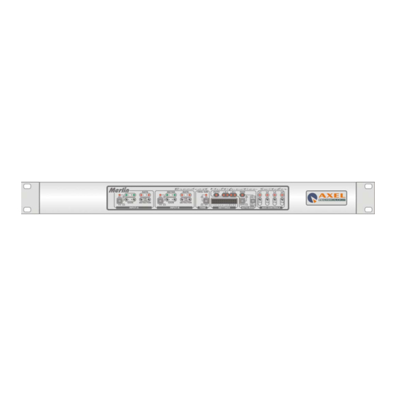
- Page 1 Operating Manual (Rel. 1.3) Merlin Broadcast Audio Changeover Via Caduti Di Sabbiuno 6/F • 40011 Anzola Emilia • Bologna • Italy +39 051 736555 • Fax. +39 051 736170 • web site: e-mail: info@axeltechnology.com www.axeltechnology.com...
-
Page 3: Table Of Contents
Merlin - TABLE OF CONTENTS 1 TABLE OF CONTENTS TABLE OF CONTENTS.............................. 3 INTRODUCTION................................. 5 MERLIN OPTIONAL MODULES ........................6 SAFETY WARNINGS ..............................7 CONNECTING MAINS POWER..........................8 EARTHING ................................8 INSTALLATION................................ 10 UNPACKING AND INSPECTION ........................10 AC MAINS VOLTAGE SETTING (220 V / 115 V).................... 10 RACK MOUNTING THE UNIT.......................... - Page 4 Merlin - TABLE OF CONTENTS 9.4.3 Momentary or Latched Relay setting ......................43 VCA OPTION ................................. 44 10.1 CROSSFADE MODE............................45 10.2 AUTOFADER MODE............................45 BLOCK DIAGRAM ............................... 46 TECHNICAL SPECIFICATIONS........................47 Pag. 4...
-
Page 5: Introduction
+ 3 dBm dB). The Merlin is very easy to install and to operate. A ‘0 dB gain’ mode can be selected for each output channel via front panel accessible slide switches. For fine calibration of the outputs, the source signal can be replaced by an internal 1kHz / 0 dB oscillator. -
Page 6: Merlin Optional Modules
Merlin - INTRODUCTION MERLIN OPTIONAL MODULES An MPX decoder is applied to the incoming MPX signals, resuming the Left and Right audio channels form the composite signal and routing them to the Input A for regular detection (see above). A pilot detector is also provided (which can be disabled), switching to the backup signal if pilot is lost. -
Page 7: Safety Warnings
Merlin - SAFETY WARNINGS 3 SAFETY WARNINGS A correct installation and an optimum level setting are crucial for a good operating and the exploitation of all the equipment capabilities. Please pay attention to the following notes: The installation and servicing instructions in this manual are for use by qualified personnel only. -
Page 8: Connecting Mains Power
Have your mains system checked by a qualified electrician. Do not remove the earth connection from the Merlin mains plug: The Merlin chassis is connected to mains earth through the power cable to ensure your safety. If problems are encountered with earth loops disconnect the audio cable screens at one end, usually at the destination. - Page 9 To connect an unbalanced source to a Merlin input (balanced), link the cold input (XLR pin 3 or jack ring) to 0V earth (XLR pin 1 or jack ground) at the Merlin side.
-
Page 10: Installation
Merlin - INSTALLATION 5 INSTALLATION UNPACKING AND INSPECTION If you note obvious physical damage, contact the carrier immediately to make a damage claim. Packed with the unit are: 1 Operating Manual 1 Line Cord Save all packing materials! If you should ever have to ship the unit (e.g., for servicing), it is best to ship it in the original carton with its packing materials because both the carton and packing material have been carefully designed to protect the unit. -
Page 11: Rack Mounting The Unit
Merlin - INSTALLATION The power supply socket has an integral fuse drawer containing the AC power fuse and a spare, both of the same value. For 220 / 230 V AC and 110 / 115 V AC tensions, the fuse is rated at 500mA T. -
Page 12: Removing The Top Cover
Merlin - INSTALLATION To mount the unit in a standard 483 mm (19-inch) audio equipment rack, slide the equipment into the rack and secure it with front crosshead screws. Use all four screws. Ventilation. Slots and openings in the product are provided for ventilation. They ensure reliable operation of the product, keeping it from overheating. -
Page 13: General Description
Merlin - GENERAL DESCRIPTION 6 GENERAL DESCRIPTION 6.1 FRONT PANEL FIX / ADJ BUTTONS It selects input source pre-amplification mode: - FIX: gain applied to input source adjustable is unitary (0 dB) and it can not be adjusted - ADJ (key pressed, Led illuminated): gain applied to input source adjustable via trimmers (2) ‘GAIN’... - Page 14 Merlin - GENERAL DESCRIPTION BUILT-IN OSCILLATOR Merlin contains an oscillator designed for system setup ad alignment and generating 1 KHz / 0 dBm tone. When TONE button is pressed all current inputs are turned off, and the sinusoidal TONE is placed on all output connectors (Left and Right). When disabled (TONE LED off), the changeover returns to its previous state (normal operation).
-
Page 15: Rear Panel
(500 mA). We suggest to use that value either for 220 Vac sources or 110 Vac source. ‘OPTO’ Designed for Merlin remote control. Ref to Section 9.2 INTERFACE RELAY Available as an option, it features 5 jumper-settable Relays. See § 9.4... - Page 16 Merlin - GENERAL DESCRIPTION UNBALANCED Depending on the button (12) selection, this pair of PinRca connectors provide an INPUT/OUTPUT unbalanced, stereo repetition of the signal appearing at the input ‘B’ XLR connectors (foldback function, via independent buffers) or serve as unbalanced input (in place of XLR balanced one).
-
Page 17: Configurations
Merlin - CONFIGURATIONS 7 CONFIGURATIONS 7.1 INPUT SWITCHING MODES (JUMPER SETTING) Merlin features several input switching modes, depending on the Jumper setting on the front panel bay. All switching modes are related to the AUTOMATIC operating mode. N° Jumper PRESENT... - Page 18 - CONFIGURATIONS With B Input selected from external command (provided through ‘opto’ interface), in the event of B failure, Merlin switches back to A in any case (even if B switching command stays on) Switching on B input is done only...
-
Page 19: Switching-Related Audio Levels
‘SILENCE’ TIME The ‘silence’ time duration before the Merlin switches or acts accordingly to operating mode set at Section 7.1 is adjustable by means of TIME trimmers (one for each input - see (4) on the front panel) in conjunction with Jumpers J1 - J 2 (Input A) and J3 –... - Page 20 Merlin - CONFIGURATIONS J 1, J2, J 3, J 4 NUMBER OF BLINKS Note: counters are reset as soon as main signal comes back to working levels. Pag. 20...
-
Page 21: Recovery Time
RECOVERY TIME Once the Merlin has switched from Main to Stand-by input, the Main input may be kept monitored till the Main audio input resumes. Also when Main audio appears, a time ranging from 0.5 to 10 seconds may be awaited before inverse switching (from B to A) is performed. -
Page 22: Mono / Stereo Input Mode
Merlin - CONFIGURATIONS 7.4 MONO / STEREO INPUT MODE The two Inputs A and B may operate either in MONO or STEREO mode. In the MONO mode, LEFT channel is mirrored on the RIGHT channel, so that the same audio material will be available on both output channels. -
Page 23: Input B Pre-Emphasys
- CONFIGURATIONS 7.5 INPUT B PRE-EMPHASYS Merlin featured a built-in 50 microsec pre-emphasys stage so that its output is made suitable for Frequency Modulated (FM) broadcast. Pre-emphasys can be associated only to B input / LEFT and/or RIGHT channels (so that ouput will be pre-emphasized when B input is routed to the output). -
Page 24: Kh Zpilot Tone Activation
Merlin features a built-in 19 KHz oscillator (pilot) suitable for stereo-like FM broadcasting** The Pilot Tone may be associated to B-Input only, so that when that Input is selected, the Merlin output will contain a 19 KHz pilot tone mixed into. -
Page 25: Injection Of An External Source
- CONFIGURATIONS 7.7 INJECTION OF AN EXTERNAL SOURCE Merlin supports injection of any external source (with frequency between 0 and 100 KHz) on input A and/or B signals. The resulting sum will be output on both PinRca and XLR output connectors. - Page 26 - CONFIGURATIONS There are THREE injection modes: • external (injected) signal appears on Merlin output only when A INPUT is selected (MODE 1) • external (injected) signal appears on Merlin output only when B INPUT is selected (MODE 2) •...
-
Page 27: Switching Between Coaxial Sources (Video, Mpx, Etc)
- CONFIGURATIONS 7.8 SWITCHING BETWEEN COAXIAL SOURCES (VIDEO, MPX, ETC) Merlin features 3 BNC connectors which, if properly jumper-set, allows switching between coaxial sources (such as MPX composite FM signals, Video sources, etc). Switching is accomplished by Relays and it follows the same rules as switching on XLR/PinRca connectors. -
Page 28: Adjustements
Merlin - ADJUSTEMENTS 8 ADJUSTEMENTS 8.1 REFERENCE TONE LEVEL AND FREQUENCY The level of internal Reference Tone (internal 1 KHz oscillator, enabled from front panel switch – see (6)) may be adjusted via P13 trimmer. By default, level is set at 0 dBm. Tone frequency is adjusted by means of P20 trimmer (default value is 1 KHz). -
Page 29: Pilot Tone Frequency
Merlin - ADJUSTEMENTS 8.2 PILOT TONE FREQUENCY Pilot Tone frequency (ref also to § 7.6) is adjustable via trimmer P5 located on the rear board. Default value is 19 KHz. Pag. 29... -
Page 30: Pilot Tone Injection Level On B-Right & B-Left Channels
- ADJUSTEMENTS 8.3 PILOT TONE INJECTION LEVEL ON B-RIGHT & B-LEFT CHANNELS Pilot tone auto-generated by Merlin and injected on B-input / Channels L & R (see Section 7.6) is adjusted from trimmers P4 and P3. P4 adjusts injection level on Right channel P3 adjusts injection level on Left channel Default level is –... -
Page 31: Level Of Injection Of An External Signal On L&R Output Channels
Merlin - ADJUSTEMENTS 8.4 LEVEL OF INJECTION OF AN EXTERNAL SIGNAL ON L&R OUTPUT CHANNELS External signal injected from BNC ‘A’, ‘B’ o ‘OUT’ connectors (see Section 7.7) is summed to A and/or B inputs with a level adjusted through P1 and P2 trimmers located on the rear board. -
Page 32: Audio And Remote Interface Description
Merlin - AUDIO AND REMOTE INTERFACE DESCRIPTION 9 AUDIO AND REMOTE INTERFACE DESCRIPTION 9.1 AUDIO CONNECTIONS 9.1.1 INPUTS The equipment features electronically balanced XLR female inputs (line level). Pin 1 Ground Pin 2 Signal (+) Pin 3 Return (-) If any balanced connection is possible, please use PinRca connectors (having set them as input connectors through the associated In/OUT switchers –... -
Page 33: Pin Rca Connector Assignment
Merlin - AUDIO AND REMOTE INTERFACE DESCRIPTION 9.1.3 PIN RCA CONNECTOR ASSIGNMENT PinRca connectors associated to XLR input connectors may be configured as fold-back output of balanced inputs (i.e. the replicate the input signal in unbalanced mode) or as alternative, unbalanced inputs. -
Page 34: Output
Merlin - AUDIO AND REMOTE INTERFACE DESCRIPTION 9.1.4 OUTPUT The equipment features XLR analog outputs electronically balanced by high- quality buffers, capable of withstanding even low-impedance loads (600Ω), with levels of up to +20 dBu. Pin 1 Ground Pin 2... -
Page 35: Opto'interface
(f.i., to control MIX mode from remote, provide the positive rail to pin 14 and Ground to pin 15, as shown on the next page table). In no external voltages are available, use the Merlin’s supplied 15 V to polarize photodiodes through a 2000 Ohm, ¼... - Page 36 Merlin - AUDIO AND REMOTE INTERFACE DESCRIPTION NOTE switching remote control is achievable ONLY while Merlin is in AUTO mode. DESCRIPTION DIRECTION Collector of photocoupler – ‘Manual’ mode engaged Emitter of photocoupler – ‘Manual’ mode engaged Not connected - 15 V...
-
Page 37: Special Switching Features
When switching is remotely controlled from the OPTO interface, two pairs of Jumpers (J8,J9 and J5,J6) allows to enable audio detecting on B Input so that, in the event no audio is detected, Merlin will switch back to A even if switching command is kept active. -
Page 38: Relay' Interface (Optional)
Merlin - AUDIO AND REMOTE INTERFACE DESCRIPTION ‘RELAY’ INTERFACE (OPTIONAL) As already notified, the ‘Relay’ interface is available as an option. It contains 5 Relays, 2 of which (Relay 4 and Relay 5, double-way type) are permanently associated to B input switching and 3 are user-assignable. -
Page 39: Relay 1, Relay 2 And Relay 3 Assignment
Merlin - AUDIO AND REMOTE INTERFACE DESCRIPTION 9.4.1 Relay 1, Relay 2 and Relay 3 assignment Three relays R1, R2, R3 are completely Jumper configurable by the user. Jumpers are located on Relay board. They (such as Relays 4 and 5) may be set in momentary or latched mode, accordingly to the associated jumpers J2, J3, J4, J5 and J6 (see Section 9.4.3). - Page 40 Relay can be associated X4-X5 to Auto/Man button switching (so that Relay with OP jumper close will reflect Merlin AUTO/MAN status). To do this, place X19 jumper on the front board in the AUTO / MAN position (see Front Board X7-X8 Leyout here below).
- Page 41 Merlin - AUDIO AND REMOTE INTERFACE DESCRIPTION X1–X2 Selected relays toggle when under-threshold signal (A input – Right X4-X5 channel) is detected. X7-X8 X1–X2 Selected relays toggle when under-threshold signal (A input – Left X4-X5 channel) is detected. X7-X8 Relays 1 to 5 are driven by Optional boards commands (Video, Serial,...
-
Page 42: Relay 1 Assignment To Dc Power Failure
Merlin - AUDIO AND REMOTE INTERFACE DESCRIPTION 9.4.2 Relay 1 assignment to Dc POWER failure Relay 1 only may be used – when properly configured – for signaling of power failure on one or both rails of internal Power Supply (+/- 15 Volt). -
Page 43: Momentary Or Latched Relay Setting
Merlin - AUDIO AND REMOTE INTERFACE DESCRIPTION 9.4.3 Momentary or Latched Relay setting Relays from 1 to 5 may be set in momentary or latched mode, accordingly to the associated jumpers J2, J3, J4, J5 and J6. With jumper closed, Relay is set as Latched... -
Page 44: Vca Option
Merlin - VCA OPTION 10 VCA OPTION VCA option board supports two operating modes: 1) CROSSFADE: it allows to perform a smooth transition between A and B (from A to B and viceversa) source . 2) AUTOFADER: as soon as B input appears, A input is faded out . -
Page 45: Crossfade Mode
Merlin - VCA OPTION 10.1 CROSSFADE MODE Crossfade transition mode from A to B and back is performed with the following jumper setting: Set on COUPLING mode Absent Set on VCA THROUGH mode Set on VCA THROUGH mode Set on MIX mode Transition times are controlled by Trimmers T1, T2, T3 and T4 located on the front panel (see Section 6.1). -
Page 46: Block Diagram
Merlin - BLOCK DIAGRAM 11 BLOCK DIAGRAM Pag. 46... -
Page 47: Technical Specifications
Merlin - TECHNICAL SPECIFICATIONS 12 TECHNICAL SPECIFICATIONS GENERAL FEATURES ∼ 3.5 Kg Weight AC Main 110 / 220 V 50 – 60 Hz Dimensions 1 Rack Unit (484 x 351 x 44 mm) Consumption 10 VA AUDIO INPUTS (1 and 2)
Need help?
Do you have a question about the Merlin and is the answer not in the manual?
Questions and answers