Chapters
Table of Contents

Related Manuals for Dosapro Milton Roy G Series

Summary of Contents for Dosapro Milton Roy G Series
- Page 1 INSTRUCTION MANUAL FOR INSTALLATION, OPERATING, AND MAINTENANCE. Pump SERIES G™ MODEL A This manual should be made available to the person responsible for installation, operating and maintenance. Date : 11/99 O / Ref : 160.0707.001. Rev. B...
-
Page 3: Table Of Contents
CONTENTS HOW TO USE THIS MANUAL ? I – DESCRIPTION I - 1. Unpacking and storage I - 2. Description I - 3. Operating principle of the pump I - 4. Accessories I - 5. Safety and health instructions II – INSTALLATION II - 1. - Page 4 VIII - SERVICING THE MECHANICAL ASSEMBLY VIII - 1 Dismantling, Reinstalling the mechanical assembly TECHNICAL CHARACTERISTICS « EC » DECLARATION OF CONFORMITY GUARANTEE LIST OF « TECHNICAL ASSISTANCE » AND « SPARE PARTS » DEPARTMENTS...
- Page 5 HOW TO USE THIS MANUAL ? IMPORTANT: You should read the following paragraphs carefully in order to understand how to use this manual efficiently. This manual corresponds to the type of pumps Note: When first reading this document, you are mentioned on the cover page.
-
Page 6: I - 1. Unpacking And Storage
PART I - DESCRIPTION Storage for more than six months I - 1. UNPACKING AND STORAGE • Store the pump in its original packaging. In addition, packaging in heat-sealing plastic cover UNPACKING and dessicant bags must be provided for. The quantity of dessicant bags should be adapted to The packaging must be carefully examined on receipt in the storage period and to the packaging volume. -
Page 7: I - 3. Operating Principle Of The Pump
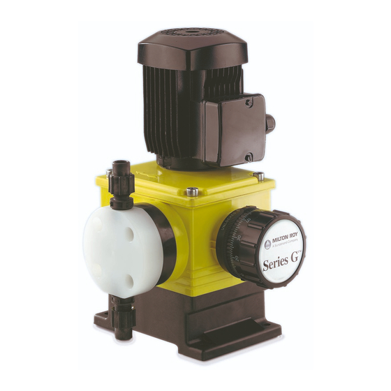
• • a drive device comprising a motor [1], Various components of the pump are shown in Figure • a mechanical assembly [2], 1.2a. • a liquid end [3]. Note: For further information on the automatic control system, see the relevant specific manual. Leak-tightness between the mechanical assembly and the liquid end is ensured by means of a bellows. -
Page 8: I - 4. Accessories
MECHANICALLY CONTROLLED DIAPHRAGM- MECHANICAL ASSEMBLY TYPE LIQUID END The mechanical assembly works on the principle of a variable eccentric. The diaphragm [7] is mechanically linked to the connecting rod [4] and has the same reciprocating The rotational motion of the motor is transmitted by the motion. -
Page 9: I - 5. Safety And Health Instructions
1 - 5. SAFETY AND HEALTH INSTRUCTIONS The personnel responsible for installing, operating and maintaining this equipment must become acquainted with, assimilate and comply with the contents of this manual in order to: • avoid any possible risk to themselves or to third parties, •... -
Page 10: Installation
PART II - INSTALLATION II - 1. HYDRAULIC INSTALLATION Note: The priming valve and the safety valve have no purpose if your pump is equipped with a 4-function valve. All the information concerning the hydraulic installation of a metering pump is detailed in a volume, «... - Page 11 Tank Injection nozzle Foot valve (equipped with a filter) Shutt-off valve Metering pump Filter Utilization Pulsation dampener 4-function valve* * In case of plastic liquid end only Provide for a safety valve on the discharge circuit in case of a stainless steel liquid end Fig.
-
Page 12: 5. Electrical Installation
II - 5. ELECTRICAL INSTALLATION For connection in SINGLE-PHASE mode, Mono see Figure 2.5d. CONNECTING THE MOTOR Replace the existing wires with those of your electrical Check the specifications of the motor and compare power supply. them with the voltage available on your installation before making connections. -
Page 13: Start Up
PART III - START UP III - 3. FAILURES ON START UP III - 1. PROCEDURES BEFORE START PROBLEMS WITH MOTOR Special care has to be taken for chemicals used in the process (acids, bases, oxiding/reducing solutions, ...). The motor runs with difficulty and heats up. See Figure 1.2a. -
Page 14: 4. Operation - Schedule Of Checks And Maintenance Operations
III - 4. OPERATION - SCHEDULE FOR The capacity is variable CHECKS AND MAINTENANCE OPERATIONS • This problem may be due to particles from the piping which interfere with the operation of the valve The programme of checks and maintenance operations assemblies: clean the piping and the valve depends on the conditions in which the equipment is assemblies. - Page 15 MAINTENANCE SHEET Pump code D.M.R. internal no. : Liquid pumped Date of commissioning Service Operation Date Hours Remarks Fig. 3.4a : Model Maintenance Sheet III - 3...
-
Page 16: Routine Maintenance
PART IV - ROUTINE MAINTENANCE • Proceed with the cleaning of the various items. In case of wear, proceed with the replacement of IV - 1. OCCURRENCE OF A LEAK the « seat - ball » assembly or of the injection FROM DETECTION PORT nozzle. -
Page 17: 5. Ordering Spare Parts
• The tangential wheel is faulty. Replace the « wheel - PROBLEMS WITH FLOW RATE connecting rod » assembly [D] (see Part VI). • A bearing is faulty. Provide for the replacement of The pump produces no flow either the « wheel - connecting rod » assembly [D], the «... -
Page 18: 1. Spare Parts Required For Annual Overhaul
PART V - PREVENTIVE MAINTENANCE ANNUAL OVERHAUL • Removing the diaphragm: Part VII - Section C1 • Removing the secondary diaphragm: Part VII - V - 1. SPARE PARTS REQUIRED FOR Section D1 ANNUAL OVERHAUL • Reinstalling the secondary diaphragm: Part VII - Section D2 •... -
Page 19: 1. List Of Other Spare Parts
PART VI - CORRECTIVE MAINTENANCE REPLACING THE « MALE ECCENTRIC » VI - 1. LIST OF OTHER SPARE PARTS ASSEMBLY This completes the list given in Chapter V - 1 which • Preliminary operations: Part VII - Section A1 covers the set of spare parts required for annual •... -
Page 20: Sequential Actions
PART VII - SERVICING THE LIQUID END AND THE LIQUID END MOUNTING ASSEMBLY Carry out the procedures described below: • in the order of the text in the case of annual overhaul (or 3,000 hours’ operation), except for the secondary diaphragm which has to be removed every two years (or 6,000 hours ’... - Page 21 B2. Reinstalling the valve assemblies B1. Removing the valve assemblies See Figure 7.2a. See Figure 7.2c.- 7.2d 1. Insert a washer [e] and a cartridge [c] 1. For the discharge circuit: Unscrew the (taking care to comply with the direction valve assembly body [14] (or the 4- of fitting) in the valve assembly body [6 function valve body).
- Page 22 Connecting rod Diaphragm Secondary diaphragm Liquid end Spacer Screw Screw Diaphragm seat Support Fig. 7.2e : Sectional view of liquid end and liquid end mounting assembly Connecting rod Spacer Stud Support Diaphragm spacer Diaphragm Washer Liquid end Spring Screw Retaining ring Diaphragm seat Secondary diaphragm Screw...
-
Page 23: Screw
D2. Reinstalling the secondary diaphragm VII - 3. REMOVING REINSTALLING THE LIQUID END AND THE LIQUID END 1. If the housing was drained, refill it (see Chapter VIII - MOUNTING ASSEMBLY 4. LUBRICATION), with the pump being laid onto the opposite side of liquid end. Remove any (Figure 7.2 e - 7.2 f) overflow oil immediately with a degreasing agent suitable for the operating conditions. -
Page 24: Diaphragm Spacer
Connecting rod Diaphragm Connecting rod Liquid end 30A Screw Screw 30B Screw Diaphragm seat Secondary diaphragm Diaphragm spacer Spacer Double diaphragm body Screw Diaphragm support Support Seal Diaphragm Seal Fig. 7.2g : Sectional view of liquid end and liquid end mounting assembly (double diapragm) Connecting rod Support Connecting rod... - Page 25 4. Position the spacer [42], placing the detection port [9] (Fig. 1.2a) facing downwards (with the VII - 4. REMOVING REINSTALLING pump in the operating position) and tighten the THE LIQUID END AND THE LIQUID screws [43] (applying a torque of 3 m.N) END MOUNTING ASSEMBLY (double 5.
-
Page 26: Washer
PART VIII - SERVICING THE MECHANICAL ASSEMBLY Base Stroke locking device Housing Half stop ring Screw (base/housing) Stroke adjustment knob Tangential wheel Cover seal Connecting rod O-ring Spring Cover Metallic plate Motor (with worm) Bearing Screw Stop bearing Screw Screw Washer Crosshead Screw... - Page 27 O2. Reinstalling the « wheel - connecting rod » VIII -1. DISMANTLING REINSTALLING assembly THE MECHANICAL ASSEMBLY 1. Where applicable, check that neither the spring (See Figure 8.2a.) [6] or the metallic plate [7] has been displaced during transportation: the spring must be at the M1.
- Page 28 TECHNICAL CHARACTERISTICS (1) Code of pump GA10 GA25 GA45 GA90 GA120 GA170 (2) Max. flow rate in l/h, at 1,5 barg Steady state accuracy (flow rate ± 2 % between 10 % and 100 %) Max. discharge pressure, in barg (3) Calibrated pressure of 4 function valve, in barg - back pressure function...
- Page 37 NO DIA 14 DE JUNHO DE 1993 (93/44 CEE) E NO DIA 22 DE JULHO DE 1993 (93/68 CEE) NO QUE SE REFERE À APROXIMAÇÃO DAS LEGISLAÇÕES DOS ESTADOS MEMBROS RELATIVAS ÀS MÁQUINAS. Nós, DOSAPRO MILTON ROY 27360 PONT SAINT PIERRE FRANCE declaramos que o material designado em seguida : está em conformidade com a directiva "máquinas" sob reserva que a instalação, utilização e manutenção sejam efectuadas seguindo as regras da arte e segundo as prescrições da nota de instruções.
- Page 38 SERIE SERIAL TYPE SERIEN SERIEÄ TIPO TYYPPI ΣΕΙ ΡΑΣ ΤΥ ΠΟΣ SARJA D2 / D4 / D6 / D10 / D17 / D34 / D50 D120 / D170 / D220 D6 / D10 / D17 / D34 / D50 Pulse D120 / D170 GA / GC / GB GA / GC...
- Page 39 GUARANTEE The vendor guarantees his products according to the The guarantee ceases : D.M.R. general conditions of sale. • if the storage of the material, outside the The vendor’s guarantee only covers the replacement or vendors factory, does not conform to his the repair, at his cost and in his factory, of all parts recommendations or to current standard acknowledged by his technical services as being...
- Page 40 FRANCE ASSISTANCE TECHNIQUE : Tél. 33.(0.2.32.68.30.02 Fax . 33.(0)2.32.68.30.96 PIECES DE RECHANGE : Tél. 33 (0)2.32.68.30.01 Fax . 33.(0)2.32.68.30.92 ACCUEIL : Tél. 33.(0)2.32.68.30.00 Fax . 33.(0)2.32.68.30.93 10 Grande Rue 27360 Pont-Saint-Pierre ,France www.dosapro.com email: contact@dosapro.com ESPAÑA ASISTENCIA TECNICA Y PIEZAS DE REPUESTOS : Tél.
Need help?
Do you have a question about the G Series and is the answer not in the manual?
Questions and answers