Table of Contents
Advertisement
Quick Links
Advertisement
Table of Contents

Related Manuals for Applied Photonics LIBS-6

Summary of Contents for Applied Photonics LIBS-6
- Page 1 Integrated Laser-Induced Breakdown Spectroscopy (LIBS) Modules User’s Manual March 2015 Doc. Ref.: UM/2020/01 Applied Photonics Ltd Unit 8 Carleton Business Park, Skipton, North Yorkshire BD23 2DE, United Kingdom Tel +44 (0) 1756 708900 Fax +44 (0) 1756 708909 Web: www.appliedphotonics.co.uk...
-
Page 2: Table Of Contents
Operating procedure Introduction Important note on back-reflections of laser radiation Step-by-Step guide to operating the LIBS equipment Shut-down procedure Operating LIBS-6 and LIBS-8 modules in “open beam” configuration Maintenance and inspection Shipping and storage Trouble-shooting / fault finding Appendices Certificate of Conformity ©... -
Page 3: Introduction
OEMs. Essentially a “LIBS system building block”, the LIBS-6 and LIBS-8 modules may be used together with a variety of Q-switched Nd:YAG lasers and optical spectrometers to form a customised, modular LIBS system tailored to suit the requirements of a specific application or experimental research project. - Page 4 IMPORTANT • READ and UNDERSTAND both this User’s Manual and the instructions provided by the manufacturer of the laser before operating the integrated LIBS module (LIBS-6 or LIBS-8) and associated laser equipment. • ENSURE that an appropriate risk assessment has been conducted to establish whether or not the laser safety windows fitted to the modular sample chambers provide adequate protection against exposure to laser radiation for the specific laser you intend to use with the LIBS equipment .
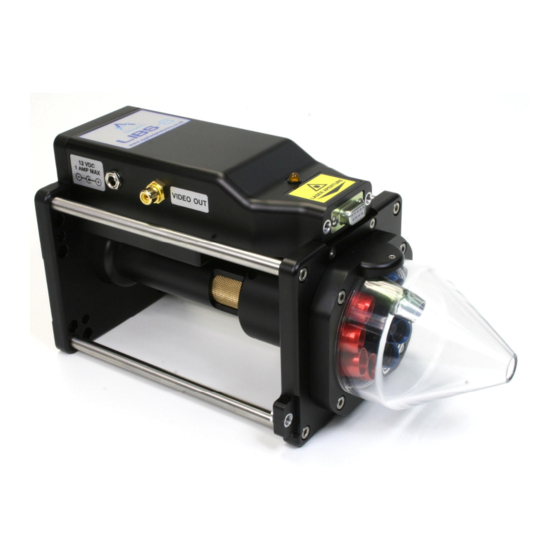
- Page 5 The function of the nozzle aperture is described later in this User’s Manual. Laser warning indicator light Laser aperture warning label Laser aperture Image of LIBS-6 module showing location of laser warning indicator light, laser aperture and warning label © 1998 - 2015 Applied Photonics Ltd Page 5 of 31...
-
Page 6: Note On The Laser Safety Window Material Used In The Modular Sample Chambers
(ie. typically less than 250 mJ with a 5 - 10 ns pulse length). Note that the protective windows are NOT suitable for use with a 532 nm laser. Given that the LIBS-6 and LIBS-8... -
Page 7: General Description Overview
General description Overview The main components of the LIBS-6 integrated LIBS module are illustrated in the following figures. The LIBS-8 module is essentially identical to the LIBS-6 module except that it has eight plasma light collection channels rather than six. - Page 8 Optional miniature CCD colour video camera with array of dimmable high-brightness white LEDs for illuminating sample surface. • Laser safety interlock with keyswitch operated override facility (via the SpectroModule-6 spectrometer). • Compatible with the Applied Photonics Ltd range of modular sample chambers. © 1998 - 2015 Applied Photonics Ltd Page 8 of 31...
-
Page 9: Laser Beam Expander And Plasma Light Collection Optics
The laser beam expander consists of three lenses and is used to provide a tightly focussed laser beam at nominally 90 mm from the aperture of the beam expander (80 mm for the LIBS-6 beam expander). The optical design is specific to the make and model of laser which the LIBS module is to be used with –... -
Page 10: Attaching The Libs Module To A Laser
The LIBS modules are suitable for use with virtually any commercially-available Q-switched Nd:YAG laser which has operating characteristics appropriate for LIBS. In order to attach either the LIBS-6 or LIBS-8 module to a laser head, it is necessary to use an appropriate adaptor platform. At the time of writing of this User’s Manual, Applied Photonics Ltd supplies adaptor platforms for the following lasers:... - Page 11 Hex C/S Hd Screws M4 x 12 Qty 3 Hex Cap Hd Screws Qty 4 LIBS-6 module fitted to Quantel Big Sky Ultra laser head using AP-Ultra adaptor platform © 1998 - 2015 Applied Photonics Ltd Page 11 of 31...
-
Page 12: Modular Sample Chambers
Modular sample chambers A range of modular sample chambers is available for use with the LIBS-6 / LIBS-8 modules (see table below). These sample chambers are also suitable for use with our LIBSCAN range of products. Two types (SC-2C and SC-2L) are described in more detail in the remainder of this User’s Manual. -
Page 13: 3.4.1 Sc-2C Modular Sample Chamber
The sample chamber is equipped with a number of features as illustrated in the following figures. Electrical connection to LIBS module Door with magnetic catch and dual electrical interlocks CAD view of SC-2C modular sample chamber © 1998 - 2015 Applied Photonics Ltd Page 13 of 31... - Page 14 Secure SC-2C sample chamber to the LIBS-6 module using the four M5 cap head screws CAD views of SC-2C modular sample chamber illustrating method of attachment to LIBS-6 module © 1998 - 2015 Applied Photonics Ltd Page 14 of 31...
-
Page 15: 3.4.2 Sc-2L Modular Sample Chamber
CAD views of SC-2C modular sample chamber attached to LIBS-6 module 3.4.2 SC-2L modular sample chamber A general view of the SC-2L modular sample chamber is given in the following figure. The sample chamber is equipped with a breadboard plate which is attached to a manual three-axis translation stage (50 mm travel per stage). - Page 16 Electrical door interlock switch X-axis adjustment knob Feet suitable for Y-axis attachment to a metric or adjustment knob imperial optical table CAD view of SC-2L modular sample chamber © 1998 - 2015 Applied Photonics Ltd Page 16 of 31...
- Page 17 CAD view of rear panel of SC-2L modular sample chamber The LIBS-8 and LIBS-6 modules are designed to fit to the top of the sample chamber using four M5 screws as illustrated in the following figures. Before fitting the LIBS module to the sample chamber, ensure that the breadboard plate is positioned sufficiently low so as not to make contact with the aperture nozzle of the LIBS module.
- Page 18 Ultra laser head head AP-Ultra adaptor plate LIBS-6 module SC-2L modular sample chamber Breadboard sample table CAD view of LIBS-6 module with Ultra laser fitted to SC-2L modular sample chamber © 1998 - 2015 Applied Photonics Ltd Page 18 of 31...
-
Page 19: Quantel Ultra Ice 450 Laser Power Supply And Interlock Override Keyswitch
Sample M6 tapped holes on 25 mm centres) Close-up view of inside of SC-2L sample chamber with LIBS-6 module fitted and showing a laser-induced plasma on a metallic sample Quantel Ultra ICE 450 laser power supply and Interlock Override Keyswitch See the Quantel’s instructions for a complete description of the ICE 450 laser power supply and cooling... - Page 20 The Interlock Override keyswitch located on the control panel of the SpectroModule-6 is used to override the laser safety interlock when the LIBS-6 or LIBS-8 module is required to be used in “open beam” configuration (ie. without a sample chamber). To override the interlock, the keyswitch should be turned “on”...
-
Page 21: Imaging Camera And Associated Components
Imaging camera and associated components The imaging camera is offered as an optional feature for both the LIBS-6 and the LIBS-8 modules (product code IMG-1). As illustrated below, a miniature colour CCD camera is located within the green tubular holder at the 12 o’clock position adjacent to the array of plasma light collection optics. The tubular holder is fitted with an optical filter to protect the CCD camera from damage due to possible high levels of stray laser light (laser wavelength must be specified when placing an order). -
Page 22: Low-Voltage Electrical Connections
“SR” (solarisation resistant) and this fibre should be used for the Deep UV (DUV) channel (ie. SPEC-1 on the spectrometer and the LIBS-6 blue lens folder at the 1 O’Clock position as viewed from the front of the LIBS-6 module). Proceeding in a clockwise manner, the remaining plasma light lens holders should be connected to the SPEC-2 –... - Page 23 ICE 450 laser power supply SpectroModule-6 spectrometer Remote Box (used for manual control of the laser) Image of LIBS-6, Ultra laser, SpectroModule-6 and SC-2L sample chamber after final assembly © 1998 - 2015 Applied Photonics Ltd Page 23 of 31...
-
Page 24: Operating Procedure Introduction
LIBS-6 module and/or laser head. Persons familiar with the use of these types of laser will appreciate that merely placing a glass window in the path of the laser beam can result in up to 4% of the laser radiation from each optical surface to be reflected back towards the laser source. -
Page 25: Step-By-Step Guide To Operating The Libs Equipment
If the sample chamber is to be used, fit the LIBS module to the sample chamber using the four M5 screws (supplied with the unit) as illustrated in the previous figures. Step 5 Connect the LIBS-6 module to the SpectroModule-6 (or alternative interface to the laser power supply) using the supplied lead. Step 6 Connect the coolant pipes and electrical cables (supplied with the laser) between the laser head and the ICE 450 laser power supply. - Page 26 If the interlock is found not to be operating correctly, refer to the Fault Finding section of this User’s Manual. Note that if the LIBS-6 module is removed from the sample chamber, the interlock circuit is designed to de-activate the laser (see section 6 on Operating instrument in “open-beam”...
- Page 27 (1 mm pitch thread) CAD view of LIBS-6 module showing method for adjusting position of aperture nozzle and laser beam focus Step 16 If using LIBSoft software to control the laser, connect the personal computer to the serial port on the front panel of the ICE 450 laser power supply using the supplied Serial-to-Serial lead.
-
Page 28: Shut-Down Procedure
Consult your Laser Safety Officer before operating the LIBS modules in this mode. Examples of a LIBS-6 module fitted to a Quantel Ultra laser and being used in “open beam” mode © 1998 - 2015 Applied Photonics Ltd... -
Page 29: Maintenance And Inspection
LIBS products. Shipping and storage The LIBS-6 and LIBS-8 modules should be kept in a clean, dry environment which is free from extremes of temperature. The module contains sensitive optical and electro-optical components and so should be protected from excessive vibration or shock. -
Page 30: Trouble-Shooting / Fault Finding
Reducing the laser pulse repetition rate and/or pulse energy and/or increasing laser beam spot size on the surface of the sample may also help. Gas purge using an inert gas such as argon will also help. © 1998 - 2015 Applied Photonics Ltd Page 30 of 31... - Page 31 Appendix A1 Certificate of Conformity Declaration of Conformity Applied Photonics Ltd declares that the product listed below has been designed and manufactured in compliance with the relevant standards as follows: Product name: LIBS-6 and LIBS-8 Integrated LIBS Modules Model Number:...
Need help?
Do you have a question about the LIBS-6 and is the answer not in the manual?
Questions and answers