Table of Contents
Advertisement
Quick Links
INSTALLATION MANUAL
AquaLink
M8
®
For One Touch and PDA control systems
WARNING
FOR YOUR SAFETY - This product must be installed and serviced by a licensed electrician in accordance
with the latest, enforced version of AS/NZS 3000 and any other applicable local installation codes.
Before installing this product, read and follow all warning notices and instructions that accompany this
product. Failure to follow warning notices and instructions may result in property damage, personal
injury, or death. Improper installation and/or operation will void the warranty.
Improper installation and/or operation can create unwanted electrical hazard which can cause serious
injury, property damage, or death.
Advertisement
Table of Contents

Related Manuals for Zodiac AquaLink M8


Summary of Contents for Zodiac AquaLink M8
- Page 1 INSTALLATION MANUAL AquaLink ® For One Touch and PDA control systems WARNING FOR YOUR SAFETY - This product must be installed and serviced by a licensed electrician in accordance with the latest, enforced version of AS/NZS 3000 and any other applicable local installation codes. Before installing this product, read and follow all warning notices and instructions that accompany this product.
- Page 2 Page 2 AquaLink M8 | Installation Manual ® EQUIPMENT INFORMATION RECORD DATE OF INSTALLATION INSTALLER INFORMATION INITIAL PRESSURE GAUGE READING (WITH CLEAN FILTER) PUMP MODEL HORSEPOWER FILTER MODEL CONTROL PANEL MODEL SERIAL NUMBER NOTES:...
-
Page 3: Table Of Contents
Page 3 AquaLink M8 | Installation Manual ® Table of Contents Section 1. Important Safety Instructions ..4 Section 5. PDA Handheld Remote Menu Flow Diagrams ......32 Section 2. System Overview ......6 Section 6. OneTouch™ Menu Package Contents ............6 Flow Diagrams ...... -
Page 4: Section 1. Important Safety Instructions
Page 4 AquaLink M8 | Installation Manual ® Section 1. Important Safety Instructions READ AND FOLLOW ALL INSTRUCTIONS The Aqualink control system is for Pool and Spa applications only. NOT FOR USE with anything other than Pool and Spa equipment. All electrical work must be performed by a licensed electrician and conform to all national, state, and local codes. - Page 5 Page 5 AquaLink M8 | Installation Manual ® WARNING People with infectious diseases should not use a spa or hot tub. To avoid injury, exercise care when entering or exiting the spa or hot tub. Do not use drugs or alcohol before or during the use of a spa or hot tub to avoid unconsciousness and possible drowning.
-
Page 6: Section 2. System Overview
AquaLink configuration you are installing. OneTouch™ PDA System • OneTouch Control Panel • PDA Handset with batteries • AquaLink M8 Power Centre • Outdoor Transceiver J-box • Two (2) Temp Sensors • AquaLink M8 Power Centre • Two (2) JVAs (Pool/Spa Combo Systems) •... - Page 7 Page 7 AquaLink M8 | Installation Manual ® Dimensions...
-
Page 8: Basic Plumbing
The intake and return JVAs turn simultaneously so NOTE When the filter system is shared (a pool/spa when the spa button is pressed on the AquaLink M8 combo), the spa water must be able to overflow back to the pool. control panel, water circulation switches between pool... - Page 9 Page 9 AquaLink M8 | Installation Manual ® 2.4.2 Booster Pump Pool Cleaner Plumbing Filter Heater Pump Make-up Booster Pump Check Valve Pool Intake Spa Intake Pool Return Spa Return Non-Booster Pump Pool Cleaner Plumbing Filter Heater Pump Filter Make-up Check Valve Pool Return...
- Page 10 Page 10 AquaLink M8 | Installation Manual ® 2.4.3 Basic Plumbing for Dual System Refer to Figure 1 when plumbing two (2) separate sets of equipment. The basic setup consists of one (1) pump, filter and heater for the pool and another set for the spa. Pool Heater Spa Heater Pump...
-
Page 11: Section 3. Installation
Page 11 AquaLink M8 | Installation Manual ® WARNING Section 3. Installation Potentially high voltages in the AquaLink Power Center Power Center Mounting can create dangerous electrical hazards, possibly causing death, serious injury or property damage. The power center should be located at or near the Turn off power at the main circuit of the AquaLink Power Center to disconnect the Power Center from equipment pad. - Page 12 TO CONTROLLER MUST BE OFF FOR AQUALINK RS MUST BE ON FOR STAND ALONE UI PUMP ADDRESS Zodiac ePump is via an RS485 cable. The cable pin out is shown below. TO CONTROLLER RS485 Wire Connections for Zodiac ePump This side connects to J1...
-
Page 13: Heater Connection
As shown in Figure 13, the 4-position dip switch is The heater connection section applies to all heaters or located at the rear of the Zodiac ePump. This dip switch heat pumps with thermostatic circuitry of 24 VAC or serves two functions - it determines what type of control less. -
Page 14: Jandy Valve Actuators
Page 14 AquaLink M8 | Installation Manual ® Wireless OneTouch Transceiver J-box Gas Heater To Pressure Gas Heater Connections Switch Note for AllButton: Terminals 1 and 2 Green - Enabled Red - Off Fireman’s Switch 4 3 2 1 4 3 2 1 6 5 4 3 2 1 10 9 8 7 6 5 4 3 2 1 From Fusible... - Page 15 Page 15 AquaLink M8 | Installation Manual ® Remove Locking Remove the 4 Large Knob and Handle Phillips Head Screws B (Common Port) Figure 15. Remove Locking Knob and Lid Screws Figure 13. Standard JVA Mounting Turn the actuator over to see into the actuator shaft. 3.5.2 Actuator Mounting There are four (4) “teeth”...
- Page 16 Page 16 AquaLink M8 | Installation Manual ® you do not have to change the cam settings from the factory Rotate the actuator shaft so the arrow mark on the settings. However, you may have to synchronize the cams. If top cam aligns with the microswitch actuator (bottom the actuator is out of synchronization.
-
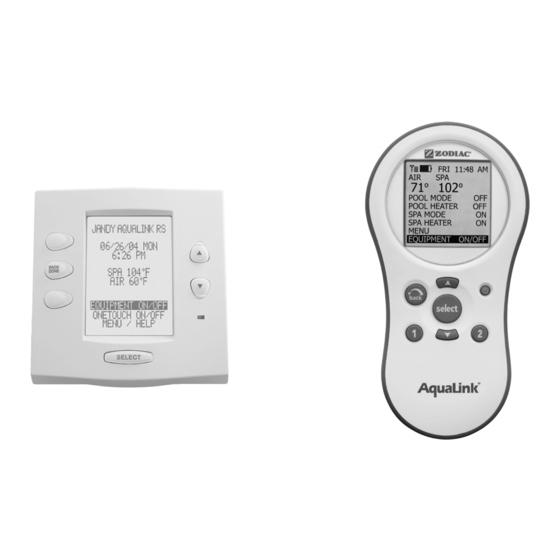
Page 17: Onetouch™ Control Panel
Page 17 AquaLink M8 | Installation Manual ® Cam Setting Chart NOTE : Before resetting cams, always rotate the actuator shaft so the arrow aligns with the pointer above its microswitch. Actuator Water Enters Port Cam Setting Water Exits Valve Mounting Common Port Top Cam... - Page 18 3.6.3 Multiple AquaLink M8 OneTouch Control Panel Installation The AquaLink M8 allows each system to support a maximum of 4 indoor control panels (see Figure 14). The control panels may be wired “in series” starting from the first control panel (solid lines), or wired “in...
-
Page 19: Section 4. System Startup
Page 19 AquaLink M8 | Installation Manual ® 1. The total length of the filtration cycle is to be from 8am to 5pm. So program the FILTER PUMP to Jumper Location turn on at 8am and to turn off at 5pm First Control Panel To run the variable speed pump at the SPEED3 setting from 8am to 1pm, highlight and select VSP SPD1 PGM, then highlight and select SPEED3, Second Control Panel... - Page 20 Page 20 AquaLink M8 | Installation Manual ® MENU/HELP > SET TEMP >MAINTAIN type in your own names. In the SET TEMP menu, highlighting MAINTAIN and NOTE The Auxiliary labels AIR BLOWER and FILL pressing SELECT will turn on (or off) the MAINTAIN LINE have an automatic 30 minute runtime.
-
Page 21: Onetouch Reset And Display Messages
Page 21 AquaLink M8 | Installation Manual ® If the system is not going to control a variable OneTouch Reset and Display ™ speed pump then leave the application set to NOT Messages INSTALLED. If the system is going to control a variable speed pump, then you would set the application 4.2.1 Restarting the System... - Page 22 Page 22 AquaLink M8 | Installation Manual ® arrow keys to highlight the desired PUMP, then press 4.3.8 Preset 2: SELECT. Use the UP/DOWN arrow keys to highlight On combo systems the default label for preset #2 either GENERAL LABELS or CUSTOM LABELS and is SPA.
- Page 23 Page 23 AquaLink M8 | Installation Manual ® On pool/spa only systems the default label is TEMP2. On a dual equipment system when a pump is configured When the pump is running and the heater set point as a POOL PUMP, the default label for preset #2 is TEMP2 is enabled, then the pump will run at this preset.
-
Page 24: Onetouch™ Systems Defaults And General Modes
System Defaults and General Modes In the event there is a power interruption, and the AquaLink M8 system is in service or time Out mode, Default Temperature (Pool/Spa Combination) the system will default to auto. In previous firmware Default Pool Temp = 80°F versions, the system would default to last mode of Default Spa Temp = 102°F... - Page 25 Page 25 AquaLink M8 | Installation Manual ® Feed the four conductor wire into the Power Center Blower or through the low voltage raceway. Transceiver Other Equipment J-Box Cut off the excess wire. Strip the jacket back 6” 8’ Min. and strip the individual wires approximately ¼”.
-
Page 26: Pda Handheld Remote System Defaults And General Modes
Page 26 AquaLink M8 | Installation Manual ® Learn Switch out of LEARN (ON) and press the 4.5.3 Changing the Frequency Channel Reset Switch. The Red and Green LEDs on the If your AquaLink RS system is turning items on or J-box will blink simultaneously (see Figure 21). -
Page 27: Pda Handheld Remote On/Off Menu
Page 27 AquaLink M8 | Installation Manual ® on or off. The ALL OFF mode will turn off equipment 4.6.2 Using the Buttons that has been turned on by any means (manual or pre- Use the buttons as explained in the diagram below. programmed). -
Page 28: Pool Heat
Page 28 AquaLink M8 | Installation Manual ® for valve rotation) and deactivates the pool cleaner if it is on. The SPA mode must be on to display the spa EQUIPMENT EQUIPMENT FILTER PUMP FILTER PUMP temperature and/or to heat the spa. Activation takes POOL HEAT POOL HEAT SPA HEAT... -
Page 29: 4.10 Solar Heat
Page 29 AquaLink M8 | Installation Manual ® FRI 10:30 PM EQUIPMENT EQUIPMENT POOL FILTER PUMP FILTER PUMP EQUIPMENT FILTER PUMP POOL MODE POOL HEAT POOL HEAT SPA HEAT SPA HEAT POOL HEATER POOL HEAT SOLAR HEAT SOLAR HEAT SPA MODE SPA HEAT AUX 1 AUX 1... -
Page 30: 4.13 Set Light Colors
Page 30 AquaLink M8 | Installation Manual ® 4.12.1 To use Heat Pump Highlight EQUIPMENT ON/OFF and press SELECT. EQUIPMENT Highlight HEAT PUMP and press SELECT. Press the FILTER PUMP POOL HEAT SELECT button to enable/disable the HEAT PUMP. The SPA HEAT SOLAR HEAT HEAT PUMP uses the SET TEMP set point. -
Page 31: 4.14 Variable Speed Pump
Page 31 AquaLink M8 | Installation Manual ® that speed setting take effect. Return to the main menu 15 seconds since the UP/DOWN keys have been pressed, then the most recently selected by using the BACK button. color will be selected again. EQUIPMENT FILTER PUMP EQUIPMENT... -
Page 32: Section 5. Pda Handheld Remote Menu
Page 32 AquaLink M8 | Installation Manual ® Section 5. PDA Handheld Remote Menu Flow Chart SELECT EQUIPMENT EQUIPMENT ON/OFF MODEL ALL OFF SERVICE SENSORS HELP DIAGNOSTICS REMOTES ADD PROGRAM POOL HEAT ERRORS SELECT DELETE PROGRAM EQUIPMENT SPA HEAT CHANGE †... -
Page 33: Section 6. Onetouch™ Menu
Page 33 AquaLink M8 | Installation Manual ® Section 6. OneTouch Menu Flow Chart ™ SPA MODE CANCEL TODAY SPRINKLERS CLEAN MODE MANUAL START SELECT EQUIPMENT ALL OFF EQUIPMENT ON/OFF ENABLE PROGRAM ONETOUCH 4 DISABLE PROGRAM ALL OFF ONETOUCH 5 MODEL ONETOUCH ON/OFF KEYS... -
Page 34: Section 7. Troubleshooting
DIP switches, switch S1-1. Turn on power and test system. first turn off all equipment. Model is one of the AquaLink M8 Normal operation when a Dual Either install the adjustable freeze sensor, or Dual Equipment, message scrolls Equipment AquaLink M8 is wait 24 hours and this message will go away. -
Page 35: Section 8. Power Center Wiring Diagram For Combos And Onlys
Spare Aux (Spa Mode) To Controller To Remote To Sensors, etc. 111 Indian Drive,Keysborough, VIC AU 3173 For technical information call Zodiac Group Australia (part of the Fluidra Group) on 1300 763 021 (red terminal bar) (brown terminal bar) (green terminal bar) CAUTION... -
Page 36: Section 9. Power Center Pcb Dip Switch Settings
With this switch on, the Turn this switch ON if you have installed a heat pump filter pump button on the AquaLink M8 control panel instead of a gas heater. After thermostat setting has been will control high speed and the AUX 2 button will reached, heater will remain OFF for 5 minutes. -
Page 37: Dip Switch Settings For Pool And Spa Combination
Page 37 AquaLink M8 | Installation Manual ® FACTORY SETTING IS WITH OFF ON ALL DIP SWITCHES OFF 4 3 2 1 4 3 2 1 6 5 4 3 2 1 10 9 8 7 6 5 4 3 2 1 RS6 &... -
Page 38: Dip Switch Settings For Pool Or Spa Only
S2 DIP Switch # The AquaLink M8 will be able to control a The AquaLink M8 will be able to control a Heat Solar Heating system (If a solar sensor is Pump. (The AquaLink M8 will not be able to control connected to the solar sensor input). -
Page 39: Dip Switch Settings For Heat Pump Installation
Page 39 AquaLink M8 | Installation Manual ® DIP Switch Settings for Heat Pump Installation This table shows how to configure the system for SOLAR PRIORITY or HEAT PUMP PRIORITY. GREEN 10-PIN TER- DIP S2-1 RS485 HEAT PUMP DESCRIPTION MINAL BAR No sensor installed Not connected In this configuration there is no Solar Heating and no... -
Page 40: Section 10. General, Water Feature And Light Aux Labels
Page 40 AquaLink M8 | Installation Manual ® Section 10. General, Water Feature and Light Aux Labels Aerator #1 Light #2 Light Air Blower #3 Light Backwash Back Light Booster Pump Chem Feed Basement Light Beach Light Cleaner Bedroom Light Color Wheel Bug Light Drain Line... - Page 41 Page 41 AquaLink M8 | Installation Manual ® NOTES...
- Page 42 Page 42 AquaLink M8 | Installation Manual ® NOTES...
- Page 43 Page 43 AquaLink M8 | Installation Manual ® NOTES...
- Page 44 219 Woodpark Road, Smithfield NSW2164, Australia 1.300.763.021 | www.zodiac.com.au ZODIAC ® is a registered trademark of Zodiac International, S.A.S.U., used under license. All trademarks referenced herein are the property of their respective owners. ©2019 Zodiac Pool Systems, Inc. H0665000 REVB...
Need help?
Do you have a question about the AquaLink M8 and is the answer not in the manual?
Questions and answers