Table of Contents
Advertisement
Quick Links
Advertisement
Table of Contents

Summary of Contents for Serial Cables PCI-ENC8G-24UM-2X2
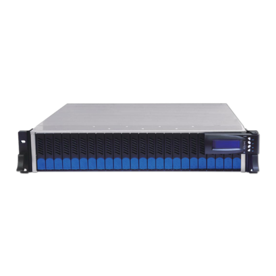
- Page 1 PCI-ENC8G-24UM-2X2 2U 24-Bay NVMe JBOF User’s Manual First edition, Mar. 2020...
-
Page 2: Table Of Contents
1. Package Checklist 2. Storage Enclosure Description 2.1 Front panel 2.2 Rear panel 2.3 Alarm Mute 3. Enclosure Installation 4. Switch Mode 4.1 mode 1 4.2 mode 2 4.3 mode 3 5. LCD Configuration LCD setup item hierarchical menu 6. CLI Manager CLI Command... -
Page 3: Storage Enclosure Description
Before the installation of the enclosure, verify that the items below are included in the package: 。A. PCI-ENC8G-24UM-2X2 enclosure × 1 。B. U.2 SSD drive tray (already installed in PCI-ENC8G-24UM-2X2) × 24 。C. U.2 SSD mounting screw × 96 。D. Power cords × 2 Optional: (number of host cards and cables depends on which mode selected;... -
Page 4: Rear Panel
2.2 Rear panel 2. Mute button 3. Link indicator LED 。To mute buzzer beeping 。Solid red – PCIe link is not at full lanes inside the enclosure 。No light – PCIe link is at full lanes 7. System status LED 4. -
Page 5: Alarm Mute
2.3 Alarm Mute As any of the following occurs, the buzzer on the switch board inside PCI-ENC8G-24UM-2X2 NVMe JBOF will beep. To mute the buzzer beeping, press PCIe switch board A and B’s mute buttons under th e LAN ports at rear of the enclosure. -
Page 6: Enclosure Installation
3. Enclosure Installation 1. Remove the UTran PCI-ENC8G-24UM-2X2 enclosure from its packaging, and place the enclosure next to computer, server, or workstation. 2. Hold one of the U.2 drive trays from the enclosure and push its button downward for the release of the lever until the lever pops out. - Page 7 5. Insert the U.2 drive module into the PCI-ENC8G-24UM-2X2 enclosure until its lever appears to shut, and then press the lever to close until it clicks to ensure that the U.2 drive module is within the enclosure.
- Page 8 Host Computer 8. The PCI-ENC8G-24UM-2X2 enclosure is with redundant PSU, so connect one end of the two power cords to the two power receptacles at rear of US_PM-2425 enclosure, and then connect the other end of the two power cords to the power outlets.
- Page 9 9. After the two power cords are connected, you can press the power button for one second on the LCD module in front of PCI-ENC8G-24UM-2X2 to power on the NVMe JBOF, and then power on the server/computer. Press it for 1 second.
-
Page 10: Switch Mode
128 Gbps, please use connection Type A for the system. Connection type A is for one server that will have access to all the twenty-four U.2 NVMe SSDs within the PCI-ENC8G-24UM-2X2 NVMe JBOF. Requirement : 1 x server, 1 x host card, 8 x... - Page 11 256 Gbps, please use connection Type B for the system. Connection type B is for one server with two host cards installed having access to all the twenty-four U.2 NVMe SSDs within the PCI-ENC8G-24UM-2X2 NVMe JBOF. Requirement :...
- Page 12 Connection Type C : Connection type C is for connecting to two servers with each server having access to twenty-four U.2 NVMe SSDs within the PCI-ENC8G-24UM-2X2 NVMe JBOF. Requirement : 2 x servers, 2 x host cards, 8 x cables Bandwidth : PCIe switch board A: PCIe Gen3 ×16, 128 Gbps...
-
Page 13: Mode 2
2. Mode 2 Mode 2 is for connecting to up to four servers with each server having access to twelve U.2 NVMe SSDs within the PCI-ENC8G-24UM-2X2NVMe JBOF. Requirement : 4 x servers, 4 x host cards, 1 6 x cables Bandwidth : PCIe switch board A: PCIe Gen3 ×32, 256 Gbps PCIe switch board B: PCIe Gen3 ×32, 256 Gbps... -
Page 14: Mode 3
3. Mode 3 Mode 3 is for connecting to up to eight servers with each server having access to six U.2 NVMe SSDs within the PCI-ENC8G-24UM-2X2 NVMe JBOF. Requirement : 8 x servers, 8 x host cards, 16 x cables Bandwidth : PCIe switch board A: PCIe Gen3 ×32, 256 Gbps... - Page 15 This section gives the info on using the front LCD module to monitor and configure the PCI-ENC8G-24UM-2X2 NVMe JBOF. The LCD module shows the display of menu, information and status. The LCD screen is able to display up to two lines at a time for menu items and other info.
- Page 16 6. PSU LED PSU normal – no light PSU failure – red 7. FAN LED Fan normal – no light Fan failure - red 8. Temp LED Temp normal – no light Over-temperature – red 9. Power LED JBOF power-on – green JBOF power-o –...
-
Page 17: Lcd Setup Item Hierarchical Menu
The following flow is an expansion of LCD setup item hierarchical menu. Fan Info Fan 1 RPM Fan 2 RPM EXIT Buttons Location Temp Info Temp 1 ℃ Temp 2 ℃ Temp 3 ℃ - Return button EXIT - Enter button PSU Info PSU 1 Temp 1 ℃... - Page 18 6. CLI Manager Users can use the Command Line Interface (CLI) to manage the NVMe JBOF functions. US_PM-2425 NVMe JBOF utilizes the USB port as the serial port interface. Please use USB Type-A male to USB Type-B male cable to connect between US_PM-2425’s switch controller and the computer/workstation;...
- Page 19 Step 1. Install and launch Tera Term program. Step 2. To ensure proper communication between PCI-ENC8G-24UM-2X2 NVMe JBOF switch controller and the VT100 Terminal emulation, please configure the VT100 Terminal emulation settings to the values as below: For “ Port ”, select COM3 .
- Page 20 Step 3. Select the Terminal emulation type, please go to the Terminal section as shown below: For “ Terminal ID ”, select VT100 . Click OK when the selection is finished.
-
Page 21: Cli Command
CLI Command This section provides detailed information about PCI-ENC8G-24UM-2X2 NVMe JBOF CLI functions. Function Command Syntax Show list of commands help help [enter] Ethernet IP configuration eth [enter] Set Ethernet MAC address setmac setmac [enter] Update PCIe switch rmware fdl sw [enter]... - Page 22 help command This command provides an online table of contents, providing brief description of the supported command groups and built-in commands. The help command can be used to get the detailed information about the CLI commands’ summary. Syntax: JBOF > help [enter]...
- Page 23 eth command Ethernet IP configuration. Syntax: JBOF > eth [enter] setmac command Set Ethernet MAC (Media Access Control) address. Syntax: JBOF > setmac [enter]...
- Page 24 Update PCIe switch firmware. For this function, the US_PM-2425 NVMe JBOF must be connected to the host computer 滾滾長江東逝水 via PCI-ENC8G-24UM-2X2’s rear USB Type-B port rather than its rear RJ-45 LAN port. Syntax: JBOF > fdl sw [enter] lsd command The command shows environmental information (temperatures, FANs, voltages) on PCI-ENC8G-24UM-2X2 NVMe JBOF.
- Page 25 showfan command The command shows FAN speed info on PCIe switch board. Syntax: JBOF > showfan [enter] buz Command The command is for controlling the buzzer on PCIe switch board. Syntax: JBOF > buz [en] / [dis] / [on] / [o ] [enter] [en]: enable the buzzer function for all time [dis]: disable the buzzer function for all time [on]: allow buzzer to beep for one time...
- Page 26 ssdpwr command The command is for controlling the power of each U.2 NVMe drive slot. Syntax: JBOF > ssdpwr [Slot No.] [on or o ] [enter] ssd_reset command To reset each U.2 NVMe SSD. Syntax: JBOF > ssd_reset [Slot No.] [enter]...
- Page 27 showslot command The command shows link speed and link width information on specific U.2 NVMe drive slot. Syntax: JBOF > showslot [Slot No.] [enter] showport command The command shows link speed and link width information on all U.2 NVMe drive slots and ports. Syntax: JBOF >...
- Page 28 setmode command The command is for setting configuration mode for PCIe switch board. Syntax: JBOF > setmode [1] / [2] / [3] [enter] [1]: set for mode 1 [2]: set for mode 2 [3]: set for mode 3 showmode command The command shows configuration mode for each PCIe switch board.
- Page 29 showtemp command The command show internal temperature of PCIe switch. Syntax: JBOF > showtemp [enter] (Applicate in Mode 4 only ) bind command The command bind any/all ports into switch group. Syntax: JBOF > bind [Slot No.] [enter]...
- Page 30 unbind command (Applicate in Mode 4 only ) The command unbind any/all ports from switch group. Syntax: JBOF > unbind [Slot No.] [enter] showbind command (Applicate in Mode 4 only ) The command show binding info. Syntax: JBOF > unbind [Slot No.] [enter]...
- Page 31 The command shows position information for switch controller board within PCI-ENC8G-24UM-2X2 NVMe JBOF. Syntax: JBOF > pos [enter] ver command The command shows controller firmware version on PCIe switch board. Syntax: JBOF > ver [enter]...
- Page 32 To reset the PCIe switch board. Syntax: JBOF > reset [enter] If you have any questions, please contact your regional distributor, or Serial Cables, LLC. Serial Cables, LLC 8811 American Way, Suite 110 Englewood, CO 80112 www.serialcables.com sales@serialcables.com...
Need help?
Do you have a question about the PCI-ENC8G-24UM-2X2 and is the answer not in the manual?
Questions and answers