Advertisement
3.75 "
AC PWR
24V ~
GROUND
LAN +
LAN –
LAN
SENSOR
SIGNAL
POWER
GROUND
U L LISTED
ENERGY MANAGEMENT
EQUIPMENT
7.50 "
POWERED BY A SINGLE
CLASS 2 SOURCE
DIN Rail
Mounting
MODEL:
Clips
SERIAL NO.:
TB4
INPUTS
POWER:
INPUT 1
INPUT 2
MADE IN USA
INPUT 3
INPUT 4
CONTROL SYSTEMS
INTERNATIONAL
+12V
P.O. BOX 59469
GROUND
DALLAS, TX
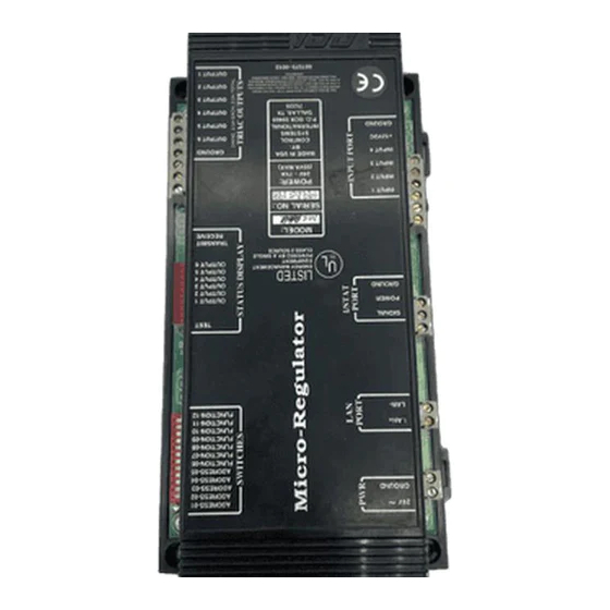
Figure 1. MR-AHU (Covered)
Controller Installation
1. Check the mounting location for the MR-AHU. The
available area must measure at least 4.3" × 8" (11.0 × 20.3
cm) and should be in a moisture free container away from
anylarge electrical devices. The screw holes are 3.75" × 7.5"
(9.5 × 19.1 cm) as shown in
(Covered)", and will require phillips or slotted pan head
screws.
Connecting the Input Devices
MR-AHU with Binary Load
AHU_2100 and Earlier:
TB4
S/P/L Contact
INPUTS
INPUT 1
INPUT 2
INPUT 3
INPUT 4
+12V
GROUND
Figure 3. Input Device Connections
Installation Sheet (TCON154 11/97)
S1
ADDRESS-01
ADDRESS-02
ADDRESS-03
ADDRESS-04
ADDRESS-05
FUNCTION-06
FUNCTION-07
FUNCTION-08
FUNCTION-09
FUNCTION-10
FUNCTION-11
FUNCTION-12
TEST
TEST
OUTPUT 1
OUTPUT 2
OUTPUT 3
OUTPUT 4
OUTPUT 5
OUTPUT 6
8.00 "
TRANSMIT
RECEIVE
MR-AHU
TB5
OUTPUTS
24V – 7VA
(55VA MAX)
BY:
GROUND
OUTPUT 6
OUTPUT 5
OUTPUT 4
75229
OUTPUT 3
OUTPUT 2
OUTPUT 1
4.30 "
Figure1, "MR-AHU
MR-AHU with Binary Load
AHU_2200 and Later:
TB4
INPUTS
Mixed Air
Temperature
INPUT 1
Sensor
INPUT 2
INPUT 3
INPUT 4
+12V
GROUND
MR-AHU Installation Sheet
.
24 VAC Power Input
AC PWR
Sub-LAN Port
LAN
I/STAT Port
SENSOR
TB4
INPUTS
Inputs
Figure 2. MR-AHU (Cover Removed)
2. You will not need to remove the plastic cover to install the
MR-AHU, or any of the connections. To replace the 4A FB
fuse, remove the plastic cover, remove the old fuse and
install a new fuse (see
Removed)").
Warning: Ensure that no power is connected to the MR-AHU
during electrical installation. Failure to disconnect
power from all interconnected equipment when
performing electrical installation may result in damage
to the components and/or electrical shock or burns
1. Connect the external input devices (contact or thermistor)
leads to an input terminal, TB4 – 1 through TB4 – 4 (Input
1 to Input 4, see
Figure3, "Input Device
2. Connect the other input device lead (common return lead)
to the signal ground terminal, TB4 – 6 (Ground).
4 A FB
Replaceable Fuse
S1
Address/Function
Select Dip Switches
Test
LED Communications
1
Indicators
2
3
4
5
6
7
8
TX
RX
TB5
OUTPUTS
Control Outputs
Figure2, "MR-AHU (Cover
Connections").
1
Advertisement
Table of Contents

Subscribe to Our Youtube Channel
Related Manuals for CSI MR-AHU

Summary of Contents for CSI MR-AHU
- Page 1 2. You will not need to remove the plastic cover to install the available area must measure at least 4.3" × 8" (11.0 × 20.3 MR-AHU, or any of the connections. To replace the 4A FB cm) and should be in a moisture free container away from fuse, remove the plastic cover, remove the old fuse and anylarge electrical devices.
- Page 2 TB2 – 2 (LAN –). GROUND 3. Shield drain wire continuity must be maintained as the sub- LAN cable passes through each MR-AHU. Shield drain wires from each controller sub-LAN cable must be twisted together, insulated, and tied back such that wires do not LAN + come in contact with ground or any conductive surface.
- Page 3 LAN + Ground Caution: Applying 24 VAC power to any connectot other than LAN – TB1 will cause component damage to the MR-AHU circuit board. Figure 7. Power Connections Switch Settings The DIP switch settings define the sub-LAN address and basic from the “Open”...
- Page 4 2 stages of heating. Specifications Dimensions Inputs/Outputs MR-AHU: 8"L × 4.3"W × 2.5"H Inputs: Digital — Dry Contact, excitation 5 V at 0.5 mA (20.3 × 10.9 × 6.4 cm) Analog — 10K Ohm NTC Thermistor, Dale 1M1002-C3 (Reference CSI TTS100 specification)
Need help?
Do you have a question about the MR-AHU and is the answer not in the manual?
Questions and answers