
Related Manuals for Teddington TSC5


Summary of Contents for Teddington TSC5
- Page 1 Bedienungsanleitung Instruction Manual T S C 5 S T E U E R U N G T S C 5 C O N T R O L L E R © Teddington Luftschleieranlagen GmbH 2019...
- Page 2 TSC5 www.teddington.de...
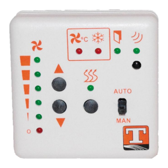
- Page 3 Steuereinheit (Bedienteil) Hand-Automatik-Umschalter (Auto/Man) DIP-Funktionswahlschalter SW1 (Steuereinheit-Bedienteil) Heizstufen-Taste ▪ SW1-1: Speicher nach LED-Anzeige Heizung Netzausfall, An oder Aus Lüfterstufen-Taste (schneller/langsamer) ▪ OFF: Nach dem Netzausfall wird die Luftschleieranlage mit der LED-Anzeige Lüfterstufe (Stop,1,2,3,4,5) zuletzt eingestellten Lüfter- und LED-Anzeige Thermokontakt Motoren Heizstufe betrieben ▪...
- Page 4 TSC5 Steuerplatine RJ-45 Anschluss für Steuereinheit (Bedienteil), maximale Kabellänge 30*) DIP-Funktionswahlschalter Meter RJ-45 Anschluss für optionale BMS (GLT) Ausgang, Betriebsmeldung Leistungsplatine (Slave), maximale (Potenzialfreier Kontakt) Kabellänge 15*) Meter Ausgang Heizung (230VAC) 0-10Volt-Eingang Steuerung Eingang Frostschutz (Potenzialfreier Zuleitung (230VAC/50 Hz) Kontakt) Eingang Türkontakt (Potenzialfreier...
- Page 5 Hand-Betrieb Stellen Sie den Hand-Automatik-Umschalter (1) auf die Position “Man-Betrieb”. Mit den Lüfterstufen-Tasten (4) wählen Sie die optimale Lüftergeschwindigkeit (schneller/langsamer). Mit der Heizungs-Taste (2) schalten Sie die Heizung ein oder aus. Wenn am Rauthermostat-Eingang (Potenzialfreier Kontakt) (12) kein Thermostat an-geschlossen ist, muss dieser Eingang mit einer Drahtbrücke überbrückt werden.
- Page 6 TSC5 Thermokontakt Motoren: Über den DIP-Funktionswahlschalter SW1-3 (20) wird die Thermokontakt-Funktion aktiviert und deaktiviert. Ist der DIP-Schalter auf ON gestellt, ist die Funktion aktiviert, bei deaktivierter Funktion wird der Thermokontakt Motor ignoriert. Die LED-Anzeige (6) leuchtet bei Auslösung eines Thermokontaktes im Motor.
- Page 7 Kabellänge Die maximale zu verwendende Kabellänge (abgeschirmtes BUS-Kabel) für den Anschluss zwischen Bedienteil und Platine beträgt bis zu 30m. Dies gilt unter Beachtung folgender Voraussetzungen: ▪ Das Kabel sollte nicht in unmittelbarer Nähe von Starkstromleitungen verlegt werden ▪ Das Kabel sollte keinen andersartigen hochfrequenten Störsignalen ausgesetzt sein Bei Verbindung von einer Master- auf eine Slaveplatine beträgt die maximale Kabellänge 15m (abgeschirmtes BUS-Kabel).
- Page 8 TSC5 www.teddington.de...
-
Page 9: Notizen / Notes
Notizen / Notes Stand 03.06.2019... - Page 10 TSC5 Control unit (operating device) Manual-Automatic switch (Auto/Man) DIP function selection switch SW1 (control unit-operating device) Heating step key ▪ SW1-1: Storage after power LED-display heating failure, On or Off Key fan steps (faster/slower) ▪ OFF: After power failure the air...
-
Page 11: Circuit Board
Circuit board RJ-45 Connection to control unit (operating device), maximum cable length DIP function selection switch 30*) m RJ-45 Connection to optional slave board, DDC/BMS output, operating message maximum cable length 15*) m (floating contact) Heating output (230VAC) 0-10 Volt-input control Supply (230VAC/50 Hz) Input frost protection (floating contact) Fan Output... -
Page 12: Automatic Mode
TSC5 If no thermostat is connected to the room thermostat input (floating contact) (12) this input must be bridged with a wire jumper. If the heating on/off key (2) is used, the power unit activates the heating output (230 VAC) (15) meaning the heating is switched on and the LED display heating (3) lights up. -
Page 13: Slave Mode
Slave mode The slave operation is selected via the DIP Function selection switch SW1-1 and SW 1-2 (20, OFF, OFF). In the Slave operation the air curtain system is operated at the speed given by the master unit. 0-10 Volt mode The 0-10-volt operation is selected via the DIP function selector switch SW1-1 and SW 1-2 (20, ON, X). - Page 14 TSC5 Cable lenght The max. cable length to be used (shielded BUS cable) for the connection between control console and board is up to 30 m. This applies under the following conditions: ▪ The cable should not be laid in the immediate vicinity of high-voltage power lines ▪...
- Page 15 Stand 03.06.2019...
Need help?
Do you have a question about the TSC5 and is the answer not in the manual?
Questions and answers