
Summary of Contents for adafruit learning system MAX9744
- Page 1 Adafruit 20W Stereo Audio Amplifier - MAX9744 Created by lady ada Last updated on 2018-08-22 03:40:27 PM UTC...
-
Page 2: Table Of Contents
Changing the I2C address Connecting to a Raspberry Pi or BeagleBone Black Python & CircuitPython CircuitPython Microcontroller Wiring Python Computer Wiring CircuitPython Installation of MAX9744 Library Python Installation of MAX9744 Library CircuitPython & Python Usage Full Example Code Python Docs Downloads Datasheets &... -
Page 3: Overview
3.5mm stereo headphone jack and jam out with ease. Since it's class D, its completely cool-running, no heat sinks are required and it's extremely efficient - up to 93% efficiency makes it great for portable or battery powered rigs. © Adafruit Industries https://learn.adafruit.com/adafruit-20w-stereo-audio-amplifier-class-d-max9744 Page 3 of 38... - Page 4 We like the MAX9744 amplifier at the heart of this board because its very easy to use, but it also has both analog and digital volume control capability. Use a single 1KΩ pot (we include one) to adjust volume analog-style. Or hook it up to your favorite microcontroller and send I2C commands to set 64-steps of volume amplification.
- Page 5 Each order comes with one MAX9744 breakout board with all surface-mount parts fully assembled and tested. We also include 3 x 2pin and 1 x 3pin terminal blocks, a 470uF power filter capacitor and 1KΩ trim pot. To use this board, a little soldering is required to attach the terminal blocks and other components, but its fairly easy and expect it should take less than 15 minutes.
-
Page 6: Pinouts
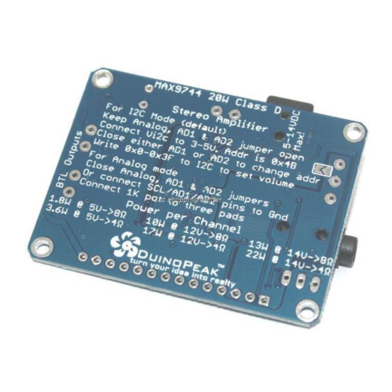
Power connections The MAX9744 amplifier can use between 5-14VDC power. The higher the voltage, the more gain you can get. So if you want 20W per channel, you'll need to supply 12VDC. The amplifier is a Class D - so it only draws current when its playing audio, but the voltage requirement is still pretty important. -
Page 7: Audio Inputs
Assembly section The MAX9744 board draws about 30-50mA quiescent current - that means that even when not amplifying audio you'll be drawing that much current from the power supply. On top of that, you have to add the current usage for audio amplification which will vary widely based on audio volume, speaker impedance, amplification, etc. -
Page 8: Speaker Outputs
You'll have to solder in the terminal blocks if you want to use that technique, see the Assembly page Speaker outputs You got this amp to amplify, and this is where you get that amplified signal out! We use two dual 3.5mm terminal blocks for the speakers, Left and Right © Adafruit Industries https://learn.adafruit.com/adafruit-20w-stereo-audio-amplifier-class-d-max9744 Page 8 of 38... -
Page 9: Breakouts
Pot. Vol - these are used in analog mode, the solder jumpers are closed to tell the chip we'll be using a potentiometer to set the volume. The Pot Vol connection is how we wire up the 1K potentiometer. This is covered in more detail in the Analog Wiring section. © Adafruit Industries https://learn.adafruit.com/adafruit-20w-stereo-audio-amplifier-class-d-max9744 Page 9 of 38... - Page 10 VDD - 5-12VDC power, from the terminal block/DC jack after the polarity protection. You can use this to power your other projects that can handle 5-12VDC power input. The solder jumper on the back allows you to connect AGND (analog ground) to DGND (digital ground) © Adafruit Industries https://learn.adafruit.com/adafruit-20w-stereo-audio-amplifier-class-d-max9744 Page 10 of 38...
-
Page 11: Assembly
We'll start with the power supply capacitor. This cap isn't required if you're powering off of batteries or a good quality supply, but if you're using wall adapter, this might give you just a little cleaner power especially with high amplification levels © Adafruit Industries https://learn.adafruit.com/adafruit-20w-stereo-audio-amplifier-class-d-max9744 Page 11 of 38... - Page 12 The longer lead goes into the pad marked + Place the capacitor against the PCB and bend the two leads out so that it sits flat. Flip over the board so you can solder the two pads © Adafruit Industries https://learn.adafruit.com/adafruit-20w-stereo-audio-amplifier-class-d-max9744 Page 12 of 38...
- Page 13 The ground (-) pin may be a little tough to solder since the ground plane acts like a large heat sink © Adafruit Industries https://learn.adafruit.com/adafruit-20w-stereo-audio-amplifier-class-d-max9744 Page 13 of 38...
-
Page 14: Speaker Terminals
You'll want to do this step, where we add the terminal blocks for the speaker outputs. Otherwise you'd have to solder wires directly to the board which isn't suggested. Place two of the 2-pin blue terminal blocks so that the holes point outward © Adafruit Industries https://learn.adafruit.com/adafruit-20w-stereo-audio-amplifier-class-d-max9744 Page 14 of 38... - Page 15 These don't have long leads to bend, so some tape can keep them in place while you solder © Adafruit Industries https://learn.adafruit.com/adafruit-20w-stereo-audio-amplifier-class-d-max9744 Page 15 of 38...
- Page 16 Flip over the board again and solder in all 4 pads. © Adafruit Industries https://learn.adafruit.com/adafruit-20w-stereo-audio-amplifier-class-d-max9744 Page 16 of 38...
-
Page 17: Power And Line In Terminal Blocks
There's also terminal blocks for Power and line-in. These are optional, you can use the DC jack and headphone jack but if you want to hard-wire in, use these instead of soldering directly to the board! Place the 2-pin and 3-pin terminal blocks so the holes point out © Adafruit Industries https://learn.adafruit.com/adafruit-20w-stereo-audio-amplifier-class-d-max9744 Page 17 of 38... - Page 18 Tape can help here, to keep the blocks in place while you solder. © Adafruit Industries https://learn.adafruit.com/adafruit-20w-stereo-audio-amplifier-class-d-max9744 Page 18 of 38...
- Page 19 Solder in all the connections Check your work before moving onto the Basic Test procedure © Adafruit Industries https://learn.adafruit.com/adafruit-20w-stereo-audio-amplifier-class-d-max9744 Page 19 of 38...
- Page 20 © Adafruit Industries https://learn.adafruit.com/adafruit-20w-stereo-audio-amplifier-class-d-max9744 Page 20 of 38...
-
Page 21: Basic Test
Next up connect 5-12VDC power to the board using a wall adapter. Then connect up an audio source. I just used a 3.5mm male/male cable to connect it to my audio player. © Adafruit Industries https://learn.adafruit.com/adafruit-20w-stereo-audio-amplifier-class-d-max9744 Page 21 of 38... - Page 22 Starting with low audio volume, slowly turn up the volume on your mp3 player/computer/etc until you hear audio come out. 20W is pretty loud so don't put the speaker next to your ear! © Adafruit Industries https://learn.adafruit.com/adafruit-20w-stereo-audio-amplifier-class-d-max9744 Page 22 of 38...
-
Page 23: Analog Control
By default, the amplifier breakout is in digital mode. To put it in analog mode we need to close the three solder jumpers labeled Analog, AD1 and AD2. Solder closed AD1 on the right side of the board Solder closed AD2 right next to AD1 © Adafruit Industries https://learn.adafruit.com/adafruit-20w-stereo-audio-amplifier-class-d-max9744 Page 23 of 38... - Page 24 Now place the potentiometer that came with your kit into the three holes labeled Pot Vol - don't solder them in yet, try to just touch the pads to the pins so that you can adjust the volume. As you twist the pot, the volume will go up and © Adafruit Industries https://learn.adafruit.com/adafruit-20w-stereo-audio-amplifier-class-d-max9744 Page 24 of 38...
- Page 25 (say mounted to the outside of a box) If you want a potentiometer that will fit exactly in the slot, check out this side-adjustment pot http://www.digikey.com/product-detail/en/bourns-inc/3362M-1-103LF/3362M-103LF-ND/1088401 For mounting onto a box or panel check out https://www.adafruit.com/products/562 (http://adafru.it/562) © Adafruit Industries https://learn.adafruit.com/adafruit-20w-stereo-audio-amplifier-class-d-max9744 Page 25 of 38...
- Page 26 © Adafruit Industries https://learn.adafruit.com/adafruit-20w-stereo-audio-amplifier-class-d-max9744 Page 26 of 38...
-
Page 27: Arduino Digital Control
Break off a piece of 0.1" male header, 14 pins long and stick it long pins down into the solderless breadboard © Adafruit Industries https://learn.adafruit.com/adafruit-20w-stereo-audio-amplifier-class-d-max9744 Page 27 of 38... - Page 28 This will keep it in place when you put the audio amplifier on top! Put the breakout board onto the short header pins so they stick out thru the breakout pads © Adafruit Industries https://learn.adafruit.com/adafruit-20w-stereo-audio-amplifier-class-d-max9744 Page 28 of 38...
-
Page 29: Connecting Up To An Arduino
Connecting up to an Arduino We'll be using an Arduino to test the digital control, but really the I2C protocol is so simple, you can easily port the code to any microcontroller you like. © Adafruit Industries https://learn.adafruit.com/adafruit-20w-stereo-audio-amplifier-class-d-max9744 Page 29 of 38... -
Page 30: Run Code
GND from the MAX9744 connects to the common ground connection on your Arduino Vi2c from the MAX9744 connects to the logic level voltage of your board. For most Arduinos, 5V works well. If you have a 3V microcontroller, use 3.3V Connect the SDA pin to the I2C data SDA pin on your Arduino. - Page 31 Upload this sketch to your Arduino, and keep it connected to your computer. Don't forget to power the MAX9744 with 5-12VDC separately via the DC jack! #include <Wire.h> // 0x4B is the default i2c address #define MAX9744_I2CADDR 0x4B // We'll track the volume level in this variable.
- Page 32 If it's OK, you can send multiple +'s and -'s to increase or decrease the volume. The volume can go down to 0 or up to 63 (which is 29dB of gain) © Adafruit Industries https://learn.adafruit.com/adafruit-20w-stereo-audio-amplifier-class-d-max9744 Page 32 of 38...
-
Page 33: Changing The I2C Address
0x4A (AD1 closed or tied to ground) or 0x49 (AD2 closed or tied to ground) Connecting to a Raspberry Pi or BeagleBone Black If you'd like to control the MAX9744 from a Raspberry Pi or BeagleBone Black then check out this Adafruit MAX9744 Python library (https://adafru.it/idA). -
Page 34: Python & Circuitpython
CircuitPython Microcontroller Wiring First wire up a MAX9744 to your board exactly as shown on the previous pages for Arduino using an I2C connection. In addition just like the basic test page mentions be sure to also wire up a power supply, speakers, and audio input to the amplifier. -
Page 35: Python Installation Of Max9744 Library
(https://adafru.it/Awz) so you are at the CircuitPython >>> prompt. Python Installation of MAX9744 Library You'll need to install the Adafruit_Blinka library that provides the CircuitPython support in Python. This may also require enabling I2C on your platform and verifying you are running Python 3. -
Page 36: Full Example Code
Below is a complete example of setting the volume of the amplifier. Save this as code.py on the board and it will set the volume to a moderate/half-way level. Full Example Code # Simple demo of the MAX9744 20W class D amplifier I2C control. # This show how to set the volume of the amplifier. # Author: Tony DiCola... -
Page 37: Python Docs
Python Docs Python Docs (https://adafru.it/C5l) © Adafruit Industries https://learn.adafruit.com/adafruit-20w-stereo-audio-amplifier-class-d-max9744 Page 37 of 38... -
Page 38: Downloads
Downloads Datasheets & Files Datasheet for the MAX9744 (https://adafru.it/dc8) Fritzing object in Adafruit Fritzing library (https://adafru.it/aP3) EagleCAD PCB files on GitHub (https://adafru.it/qpd) Schematic Layout Dimensions © Adafruit Industries Last Updated: 2018-08-22 03:40:21 PM UTC Page 38 of 38...
Need help?
Do you have a question about the MAX9744 and is the answer not in the manual?
Questions and answers